Instruments
PLASTIC LIMIT
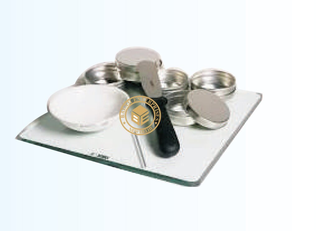
MODEL: BE-GT-002 IS 2720 (PART-VII) ASTM D 427, BS 1377, AASHTO T 92. Shrinkage limit is the maximum water content at which a reduction in water content does not cause an appreciable reduction in volume of the Soil Mass. At shrinkage limit, on further reduction in water, air enters in to the voids of soils and thus keeps the volume constant. The apparatus can be used to determine shrinkage limit and to calculate other shrinkage ratio, shrinkage index and volumetric shrinkage.
Specification :
Set consists of one each :-
I) Porcelain evaporating dish,
ii) Shrinkage dish,
iii) Glass cup,
iv) Perspex plate with three metal prongs,
v) Flexible spatula 100mm,
vi) Glass cylinder,
vii) 25ml x 1ml, supplied without mercury
LINEAR SHRINKAGE MOULD
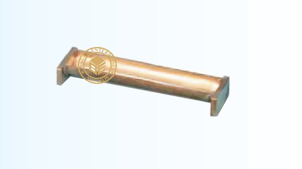
MODEL: -GT-003 BS 1377-2 A simple mould which is filled with the soil under test. This is then dried and the resulting decrease length of the specimen measured is expressed as the linear shrinkage. It is 25mm Dia. x 12.5mm Height x 140mm Length.
SOIL CONE PENETROMETER
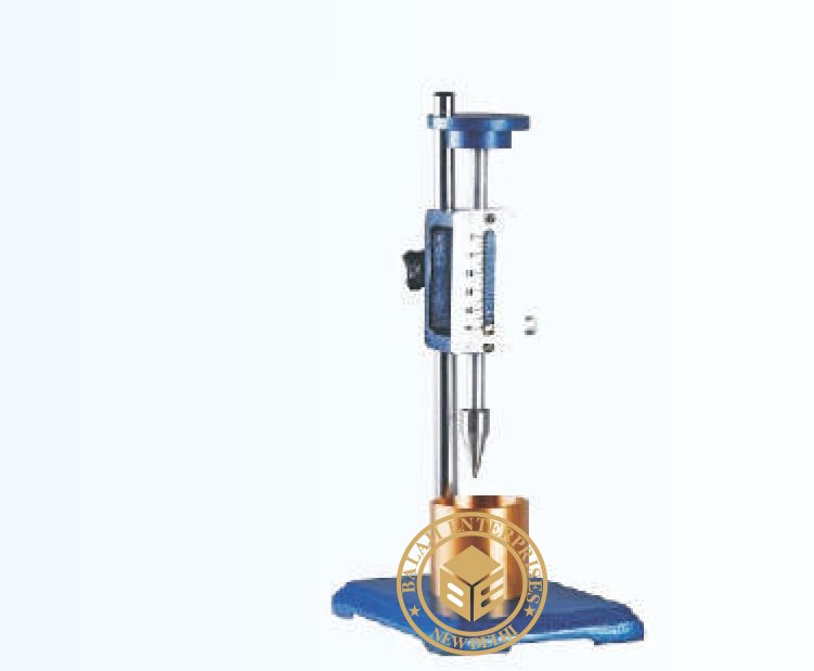
MODEL: -GT-004 IS 2720 (PART IV) For determining the liquid limit of soils. This is specially useful to obtain reliable and accurate results of those soil which have low plasticity index. The percentage moisture contents determined when cone with half angle for 15-30 minutes under a total sliding weight of 148 gm penetrates 25mm gives the liquid limit.
SOIL HYDROMETER
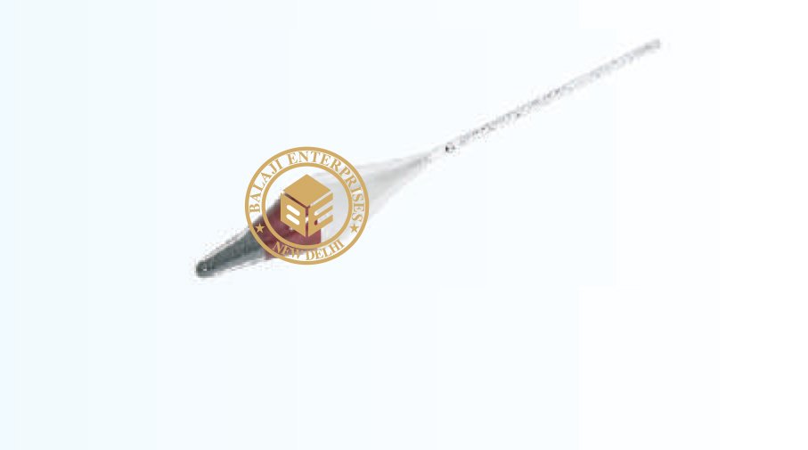
MODEL: -GT-005 ASTM D 422 AASHTO T 88, BS 1377-2. Used for grain size analysis of soils where more than 10% of the material will pass through 75 microns B.S. sieve. Manufactured from clear transparent glass having uniform clarity throughout the upper end on which density scale is engraved. The scale range is 0.995 to 1.030 0 density (gms./cc) at 27oC smallest division on the scale is 0.0005.
LIQUID LIMIT DEVICE
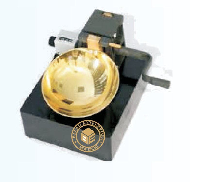
MODEL: -GT-006 IS 2720 (PART V), BS 1377-2 , ASTM D 4318 Casagrande method in mechanical form is known as liquid limit method and has been in use for soil mechanics for a number of decades. The liquid limit data of soils is useful to correlate mechanical properties of soil, such as compressibility and lower shear strength. Liquid limit is the water content at which soil passes from zero strength to an infinite strength, hence the true value of liquid limit cannot be determined. For determination purpose liquid limit is that water content at which a part of soil, cut by a groove of standard dimensions, will flow together for a distance of 1.25cm under an impact of 25 blows in a standard liquid limit apparatus. The soil at the water content has some strength which is about 0.17N/cm. sq. (17gms/sq.cm.) . At this water content soil just passes from liquid state to plastic state. It consists on a brass cup held on an adjustable bracket. The cup can be adjusted for a fall of 1 cm and can be raised an dropped on a rubber base of standard hardness by cam action. Complete with one Casagrande grooving tool, one ASTM grooving tool and a height gauge block.
LIQUID LIMIT DEVICE (WITH COUNTER)
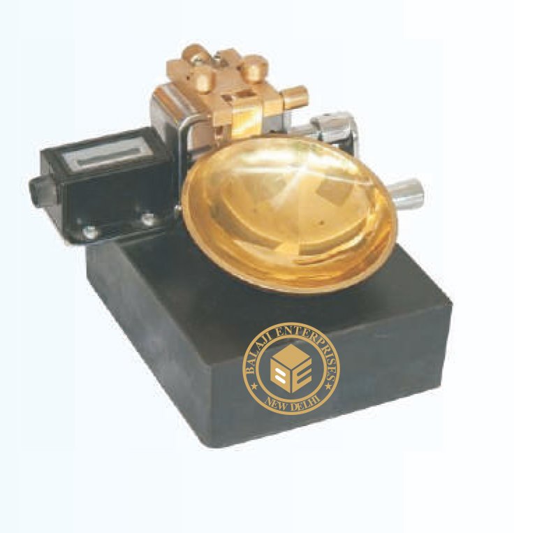
MODEL: -GT-007 IS 2720 (PART V), BS 1377-2 , ASTM D 4318 Casagrande method in mechanical form is known as liquid limit method and has been in use for soil mechanics for a number of decades. The liquid limit data of soils is useful to correlate mechanical properties of soil, such as compressibility and lower shear strength. Liquid limit is the water content at which soil passes from zero strength to an infinite strength, hence the true value of liquid limit cannot be determined. For determination purpose liquid limit is that water content at which a part of soil, cut by a groove of standard dimensions, will flow together for a distance of 1.25cm under an impact of 25 blows in a standard liquid limit apparatus. The soil at the water content has some strength which is about 0.17N/cm. sq. (17gms/sq.cm.) . At this water content soil just passes from liquid state to plastic state. It consists on a brass cup held on an adjustable bracket. The cup can be adjusted for a fall of 1 cm and can be raised an dropped on a rubber base of standard hardness by cam action. Complete with one Casagrande grooving tool, one ASTM grooving tool and a height gauge block. Same as above but fitted with a counter to register the number of blows.
LIQUID LIMIT DEVICE (WITH COUNTER)
MODEL: -GT-007 IS 2720 (PART V), BS 1377-2 , ASTM D 4318 Casagrande method in mechanical form is known as liquid limit method and has been in use for soil mechanics for a number of decades. The liquid limit data of soils is useful to correlate mechanical properties of soil, such as compressibility and lower shear strength. Liquid limit is the water content at which soil passes from zero strength to an infinite strength, hence the true value of liquid limit cannot be determined. For determination purpose liquid limit is that water content at which a part of soil, cut by a groove of standard dimensions, will flow together for a distance of 1.25cm under an impact of 25 blows in a standard liquid limit apparatus. The soil at the water content has some strength which is about 0.17N/cm. sq. (17gms/sq.cm.) . At this water content soil just passes from liquid state to plastic state. It consists on a brass cup held on an adjustable bracket. The cup can be adjusted for a fall of 1 cm and can be raised an dropped on a rubber base of standard hardness by cam action. Complete with one Casagrande grooving tool, one ASTM grooving tool and a height gauge block. Same as above but fitted with a counter to register the number of blows
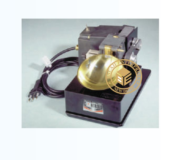
LIQUID LIMIT DEVICE (MOTORIZED)
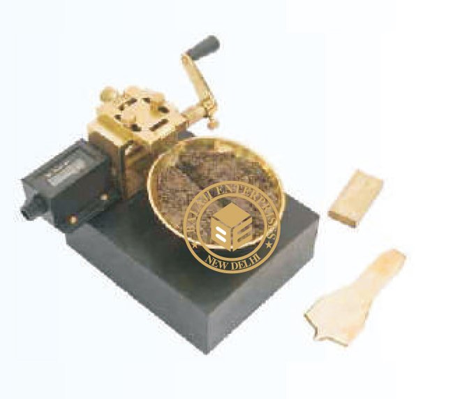
MODEL: -GT-008 Same as above but fitted with a motor geared down to give approximately 120 rpm. Suitable for operation on 230 V A.C., Single Phase, 50 Cycles. SPARES : Casagrande grooving tool. ASTM grooving tool, height block, 1cm high.
MARSH CONE
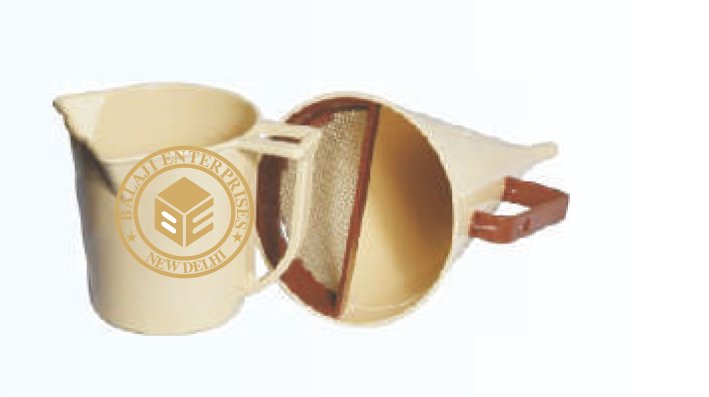
MODEL: -GT-009 ASTM D 2419, AASHTO T 176 This cone is used to find out viscosity of bentonite slurry and similar material. The marsh cone is 6 inch in diameter at the top and 12 inch long, and tapers to join a tube 2 inch long and 3/16 inch inside dia. The capacity of the funnel is 1500cc. Time in seconds required to flow out 1000cc of slurry from cone is measured as funnel viscosity of the material.
MUD BALANCE
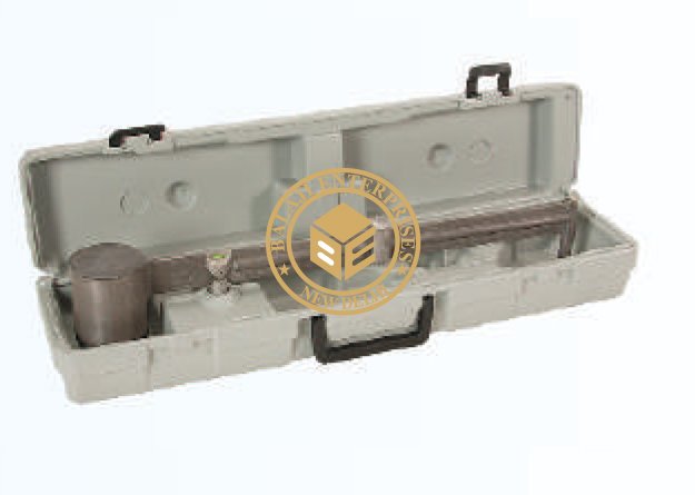
MODEL: -GT-010 ASTM D 2419, AASHTO T 176 Designed to find out specific gravities of semi liquids like mud and other liquids having densities in the range 0.8 to 2.5. It has a stainless steel bam calibrated specific gravities from 0.8 to 2.5. A stainless steel cup with lid and overflow vent is fitted on one side of the beam. A counter weights with cursor slides over the graduated scale. The beam has a knife-edge at centre which rests in a fulcrum fitted in the stand. Leveling screws and spirit level are fitted to the stand.
HIGH SPEED STIRRER
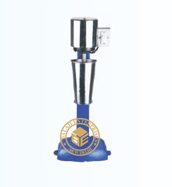
MODEL: -GT-011 IS 2720 (PART IV) This is for mechanical analysis and also other laboratory applications for stirring Speed approximately 4000 R.P.M. under load. A dispersion cup is supported on a rest on the stand of the stirrer and has a removable baffle. For operation on 230V A.C. supplied with dispersion cup or baffle cup.
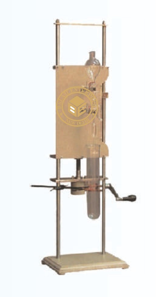
GRAIN SIZE ANALYSIS (PIPETTE METHOD)
MODEL: -GT-012 IS 2720 (PART IV) AND BS 1377:2. This is for the determination of the sub sieve particle distribution in a soil sample by mechanical analysis. An analysis of this kind expresses quantity the proportions by weight of the various sizes of particles present in the soil. It is recommended as a standard procedure to use dispersion agent to avoid flocculation. The apparatus consists of a sliding panel which moves up and down by means of a screw allowing Anderson pipette fixed to it to be raised or lowered vertically. A sedimentation tube is held by a laboratory clamp provided on the stand below the pipette. The depth of immersion is measured by a scale graduated in mm at the side of the sliding panel. Supplied complete with Anderson pipette 10ml. At the side capacity made from glass, and a sedimentation tube also of glass of 500ml capacity and 50nos. Test form pads.
ACCESSORIES And SPARES :
i) Sedimentation Pipette (Andersonpipette) 25ml,
ii) Sedimentation tube 100ml,
iii) Sedimentation pipette 10ml,
iv) Sedimentation tube 500ml,
v) Test forms pad of 50
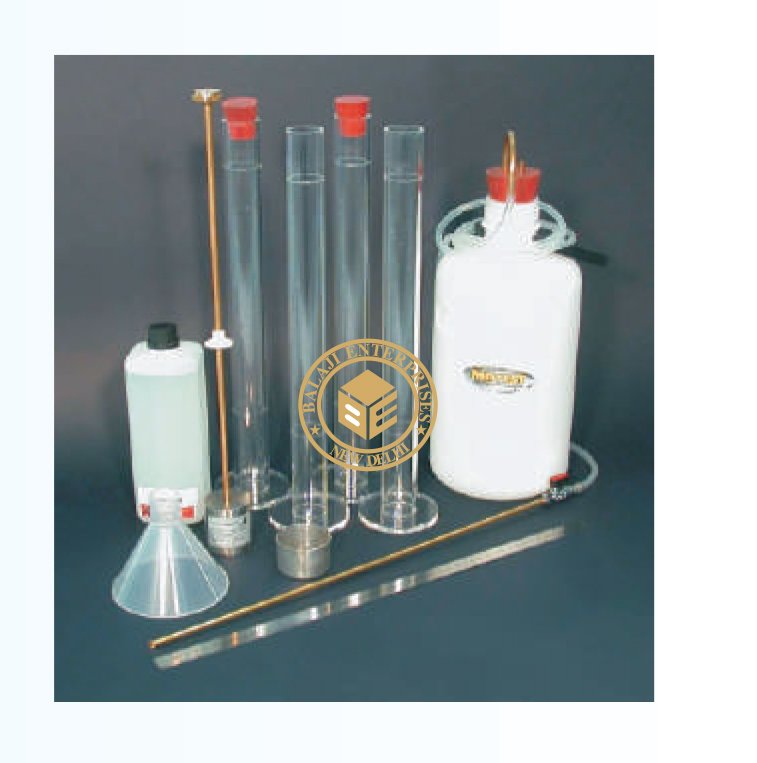
SAND EQUIVALENT TEST SET
MODEL: -GT-013
ASTM D 2419, AASHTO T 176
Used to determine the relevant proportions of clay-like or Plastic fines and dust in
granular soils & fine aggregate Consists of:
1. Acrylic graduated cylinder (4 nos.)
2. Rubber stopper for cylinder (4 nos.)
3. Graduated Steel rule 450 mm
4. Funnel 100 mm plastic
5. Aspirator bottle 5 lts plastic with rubber cock
6. Stand for the aspirator bottle with siphon assembly
7. Irrigation tube with stop pinch cock & weighted foot assembly
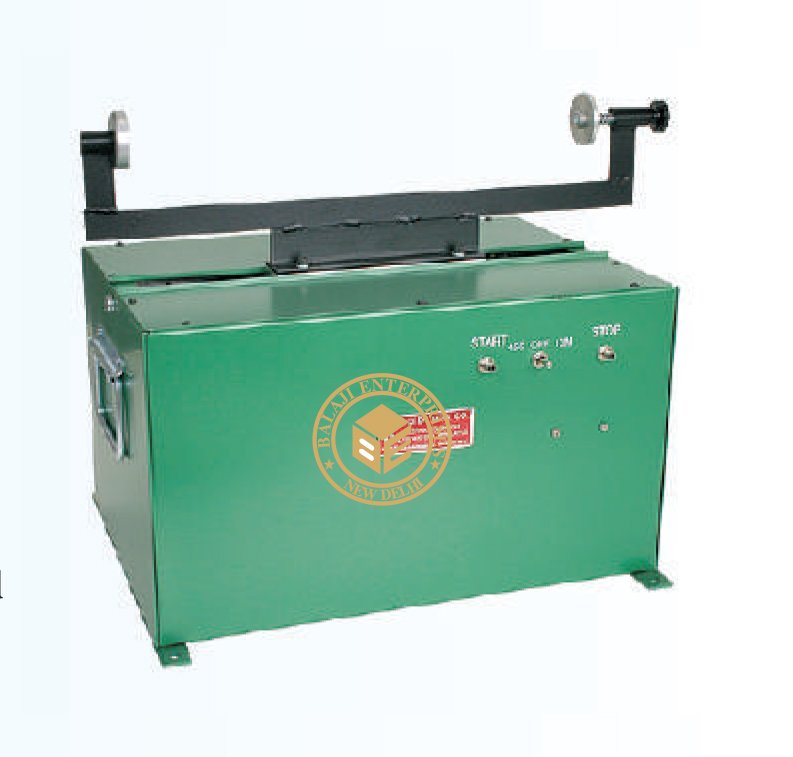
MOTORIZED SAND EQUIVALENT SHAKER
MODEL: -GT-014
ASTM D 2419, AASHTO T 176
Sand equivalent tests serve as rapid field-correlation tests to show relative
proportions of clay-like or plastic fines and dusts in granular soils and fine
aggregates. The test separates sand and clay, a comparative reading is
determined between the suspended clay and the settled sand in the measuring
cylinder. Tests may be done in the laboratory or the field. Motorized sand
equivalent shaker features two separate electronic timers (one preset at 45
seconds and the other preset at 10 minutes) to increase accuracy and ease of
operation compared to a spring-type timer. It is recommended for samples in
the laboratory.
The consistent, repeatable oscillation of the apparatus eliminates operator-caused
variation. Shaking operation delivers an 8″ (203mm) stroke at a speed of 175
±2 strokes per minute. Dimensions: 12 x 24 x 24″H (31 x 61 x 61cm).
PROCTOR COMPACTION TEST APPARATUS
MODEL: -GT-016
As Per IS: 2720 (P-VII)
Specification :
Soil compaction is of utmost requirement for constructing earth fill for dams,
canal embankments, reservoirs, highways, runways and railways. The relationship
between soil moisture content and compacted dry density largely determine the
construction specifications and quality control of compacted earthfill. To check the
strength of the soil the density of the soil is taken into account and hence the quality
control is checked otherwise.
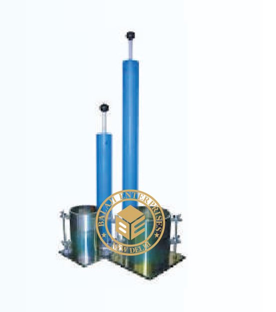
SEMI AUTOMATIC COMPACTOR
MODEL: -GT-017
IS 2720 (PART VII and VIII)
Now a days almost every soil laboratory conducts compaction and penetration tests on soils.
In both standard and heavy compaction tests the operator has to count the number of blows
of the rammer on each layer of soil during compaction. A mechanically cum electrically
operated semi-automatic compactor is therefore deviced to eliminate hand compaction process.
Which also considerably saves time with the Rammers provided two stroke lengths, available,
the compactor can be used for normal compaction/heavy compaction as well as C.B.R
compaction.
Specification :
It is a motor driven mechanical compactor useful for soil compaction into 100mm or 150mm
diameter moulds. Two sets of Rammers are provided, one of 2.6 kg and arranged for 310mm
drop and other 4.89kg and arranged for 450mm drop. For compaction soil into 150mm dia
moulds, 100mm face dia Rammers having weight 2.6kg and 4.89kg are used. Where as for
100mm dia moulds they are of 50mm dia. The rammer assembly is provided with a ratchet
and pawl arrangement to lift it from the top of the soil layer. When the rammer ratchet and
pawl arrangement to lift it from the top of the soil layer. When the rammer reaches the
required height the pawl release the rammer which falls freely on soil surface. The release
mechanism is operated by an arm moving up and down which is connected to a reduction
gear coupled to the motor through another arm. An automatic blow counter fitted to the
compactor is used to set the number of blows. The base plate of the specimen mould is to
be fitted to the rotating base plate of the instrument which marks 1/5″ revolution per stroke.
The equipment is suitable for operation on 230 Volts, 50 cycles, Single Phase, A.C. Supply
moulds are to be ordered separately.
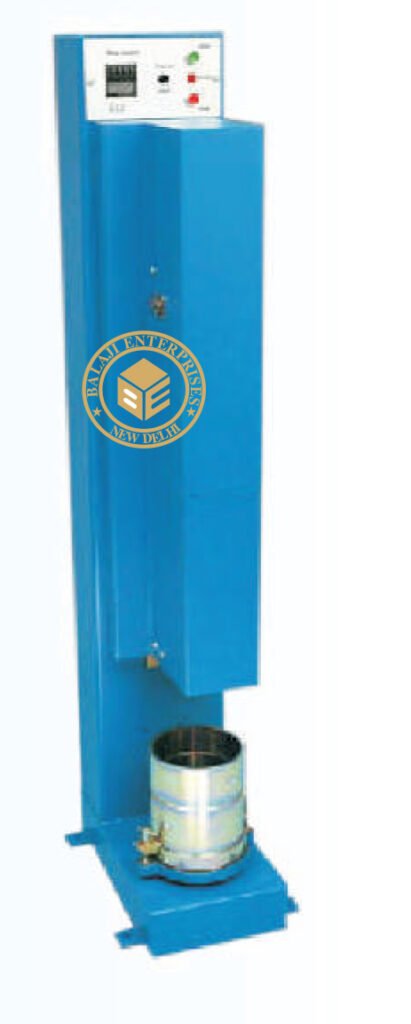
UNIVERSAL AUTOMATIC COMPACTOR
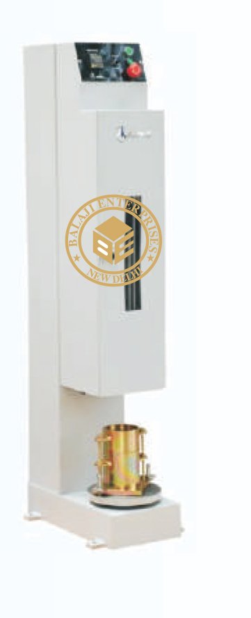
MODEL: -GT-018
ASTM D 558, BS 1377-4
It is a motor driven mechanical compactor useful for soil compaction into 100mm to 102 mm
and 150mm to 152.4 mm diameter moulds. Two sets of Rammers are provided, one of 2.5 kg
and arranged for 300 mm and 305 mm drop and other 4.5 kg and arranged for 450 mm and
457 mm drop. The rammer assembly is provided with a ratchet and pawl arrangement to lift
it from the top of the soil layer. When the rammer reaches the required height the pawl release
the rammer which falls freely on soil surface. The release mechanism is operated by an arm
moving up and down which is connected to a reduction gear coupled to the motor through
another arm. An automatic blow counter fitted to the compactor is used to set the number of
blows. The base plate of the specimen mould is to be fitted to the rotating base plate of the
instrument which marks 1/5″ revolution per stroke. The equipment is suitable for operation on
230 V, 50 Cycles, Single Phase, A.C. supply moulds are to be ordered separately.
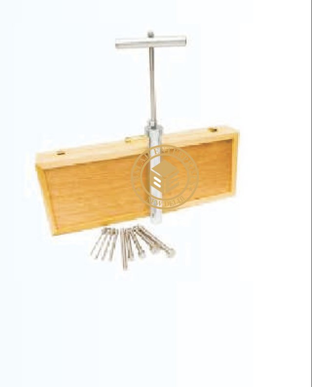
PROCTOR NEEDLES (SPRING TYPE)
MODEL: -GT-019
ASTM D 1558
The instrument consists of a needle attached to a spring loaded plunger, the stem of
which is calibrated to read 0 to 40 kg division. Long stem is graduated at every 12.5mm
to read depth of penetration and for use with needles of larger areas. The small
penetration stem is also graduation in 12.5mm division and is used with needles of
smaller areas. Needle points one each of 0.25, 0.5, 1.0, 1.5, 2.0, 3.5 and 6.0 sq Cm.
And one tommy pin is supplied. Complete as above in a wooden carrying case.
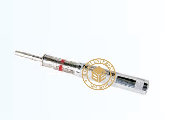
POCKET PENETROMETER
MODEL: -GT-021
ASTM D 1558 D 2573
This instrument is used to estimate approximate unconfined compressive
strength and the estimation to shear strength of soil Cohesive soils can also
be classified in terms of consistency using this Penetrometer. This is a handy
and convenient instrument.
Specification :
It consists of a light weight barrel assembly with a polished and ground steel
loading piston plunger. A direct reading scale is engraved on the piston barrel
and indicates load in kg. / sq. cm. A maximum load indicator ring is provided
on the penetration plunger. The calibrated spring is heat treated and plated for
rust resistance. The barrel diameter is 20mm and the length 150mm. Supplied
with carrying case.
VICKSBERG PENETROMETER
MODEL: -GT-022
ASTM D 1558 D 2573
This is fork determining the bearing capacity of sub grades or for compaction
control. It also used for rapidly of soils in shallow exploration work.
Specification :
Consists of a study handle under. Which is fixed a sensitive proving ring. An
extension piece is fixed to the bottom of the proving ring and carries a detachable
penetration cone at its tip. Proving ring capacity 100 kg (1kn) and 0.002mm dial
gauge provided indicates the penetration load applied.
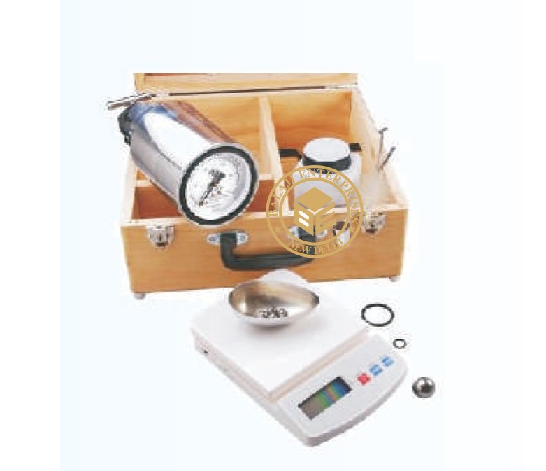
SPEEDY MOISTURE METER
MODEL: -GT-023
As Per IS 2720 (P-II), ASTM D 4944 AASHTO T 217
Specification :
Moisture content of soil is generally measured as a ratio of the weight of water
to the weight of solids, expressed in percentage. As soil behavior depends on its
moisture content, it is one of the basic parameters defining the soil condition.
The ‘Moisture’ content of soil, can be obtained quickly with reasonable accuracy
by using a Speedy Moisture Meter. The test technique is based on the fact that
water will react with calcium carbide to form acetylene gas. The quantity of
acetylene gas produced is indicated on a built- in pressure gauge. A conversation
formula gives the corresponding moisture content based on dry weight. Each soil
test equipment is supplied complete in a wooden carrying case consisting of
pressure vessel with clamp for sealing cap, rubber sealing gasket, pressure
gauge in percentage moisture content 0- 25% or 0-50% on the wet weight basis
(6 gm) counter poised balance for weighing samples, scoop for measuring calcium
carbide, bottle of calcium carbide (500gm), a set of 4 steel balls and a cleaning brush.
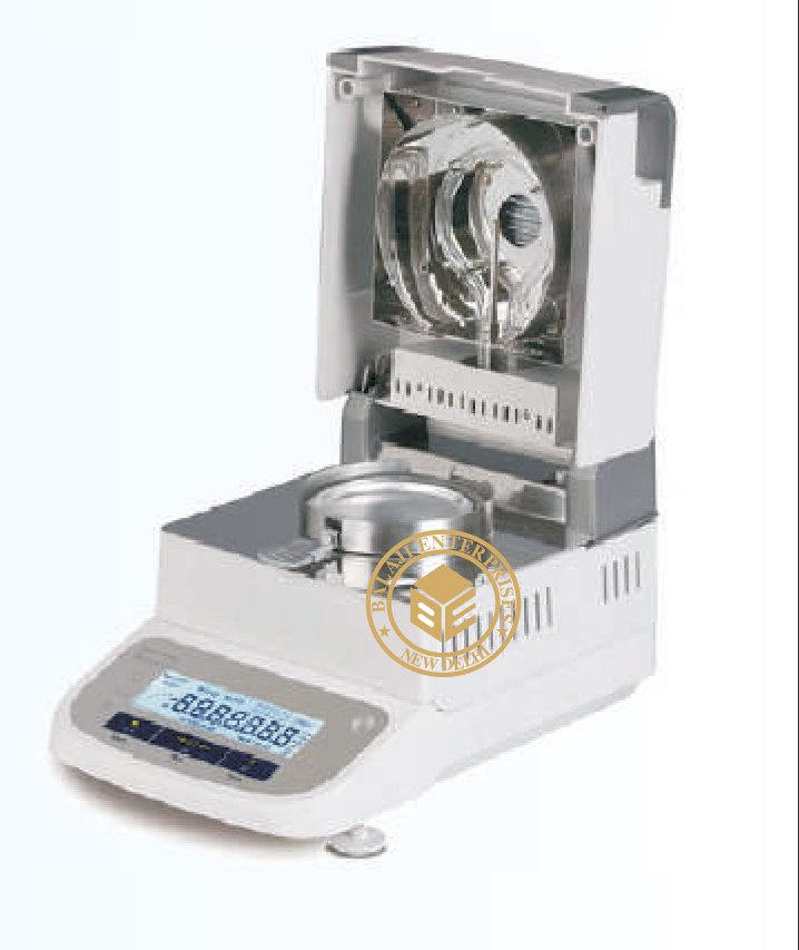
INFRARED MOISTURE METER
MODEL: -GT-025
ASTM D 4944 AASHTO T 217
This moisture meter has been designed for rapid and accurate determination of
the moisture content of a wide variety of materials. It is torsion wire instruments,
the torque being applied to one end of the wire be means of a calibrated drum to
balance the loss of weight as the test sample dries under infrared radiation. The
speed of drying (about 30 min) thus obtained, combined with the frictionless
balancing system gives the result as accurate as those obtained by standard oven
drying method. Since drying weighing are simultaneous, it is useful specially for
determination of moisture in substances that quickly reabsorbs moisture after drying.
The infrared radiation is controlled by a voltage regulator and thereby provided
excellent heat control. The instrument is provided with an indicator lamp, which
glows when the unit is switched on. The torsion balance has a built-in magnetic
damper or reduce pan vibrations that enables quick weighing. The balance scale
(drum) is divided in terms of moisture percentage on wet weight basis, which are
read directly from it. Graduations are from 0 to 100% in 0.2 % divisions, but
readings may be estimated to 0.1% moisture content. Suitable for operation on 220
V, 50Hz, Single phase, AC Supply.
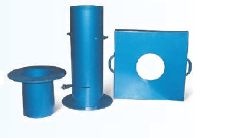
SAND POURING CYLINDER
MODEL: -GT-026
As Per IS 2720 (P-XXVIII) BS 1377-9
Specification :
The soil testing equipment is used for determination of the dry density of compact,
fine, medium grained soils and for layers not exceeding 50cm thickness. A circular
hole is dug into the ground, all the soil from within it collected, weighed and dried,
and the hole back filled with a standard uniform sand or fine gravel, poured from
a calibrated container for calculating the volume of hole. The complete apparatus
consists of a Sand Pouring Cylinder fitted with Conical funnel and Shutter,
Cylindrical Calibration Container, and a Metal tray with a central hole.
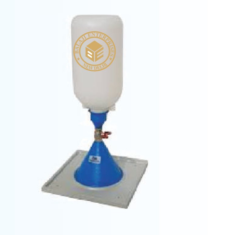
SAND DENSITY CONE APPARATUS
MODEL: -GT-027
ASTM D1556, AASHTO T191
The Sand Density Cone and accessories are used for determination of
the insitu (in-place) density of soils. The apparatus is restricted to tests
in soils containing particles not larger than 2″ (50.8 mm) in diameter.
The Sand Density Cone consists of a double cone assembly with a brass
valve and comes supplied with a one-gallon (4,000 cm3) capacity sand jug.
The Field Density Plates are used in conjunction with the Sand Density
Cones. The center opening of the plate can be used as a template to
control the diameter of the hole and the plate itself is used as a shelf to
prevent the loss of soil during the removal operation.
CORE CUTTER
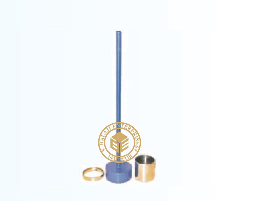
MODEL: -GT-028
IS 2720 (PART XXIX) 1966 & BS 1377-9
This is used for determination of in situ dry density of natural or compacted
fine grained soil, free from aggregates. A cylindrical cutter is used to extract
a sample of the soil with the help of a dolly and rammer. From the weight,
density and the moisture, and dry density of the soil is ready calculated. It
consists one each of: cylindrical core cutter mode of steel, 127.3mm. Long
and 100mm internal diameter. Steel dolly, 25mm high with a lip to enable it
to be located on top of the core cutter, rammer with detachable steel rod.
SPARE, OPTIONAL EXTRA AND ACCESSORIES:-
1. Cylindrical core cutter 100mm i.d. x 175mm long
2. Dolly
3. Test form pad of 50.
PERMEABILITY-CONSTANT HEAD TEST
MODEL: -GT-028
IS 2720 (PART XXIX) 1966 & BS 1377-9
This is used for determination of in situ dry density of natural or compacted
fine grained soil, free from aggregates. A cylindrical cutter is used to extract
a sample of the soil with the help of a dolly and rammer. From the weight,
density and the moisture, and dry density of the soil is ready calculated. It
consists one each of: cylindrical core cutter mode of steel, 127.3mm. Long
and 100mm internal diameter. Steel dolly, 25mm high with a lip to enable it
to be located on top of the core cutter, rammer with detachable steel rod.
SPARE, OPTIONAL EXTRA AND ACCESSORIES:-
1. Cylindrical core cutter 100mm i.d. x 175mm long
2. Dolly
3. Test form pad of 50.
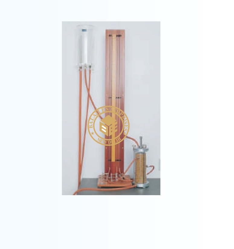
PERMEABILITY-FALLING HEAD TEST
MODEL: -GT-029
As Per IS 2720 (Part XBII)- 1966 BS 1377; EN DD ENV 1997-2; ASTM D2434; AASHTO T215
This equipment is used for testing the permeability of granular soils
(sands and gravels).The specimen is formed in a permeability cell and
water is passed through it from a constant level tank Take-off points
located along the sides of the permeability cell are connected to three
manometer tubes mounted on a panel complete with a metre scale.
Water passing through the specimen is collected and measured, either
for a specific quantity or over a period of time. The reduction of head
is noted from the variation of water level in the manometer tubes.
Comprising three glass tubes of constant bore, metre scale and
connecting tubing for cell pressure take-off points, all mounted on a
free-standing panel. Manufactured from transparent plastic with
attachment for wall mounting. The inlet, outlet and overflow pipes
are fitted to the base of the tank and can be adjusted for height within
the tank. Supplied complete with connecting tubing.
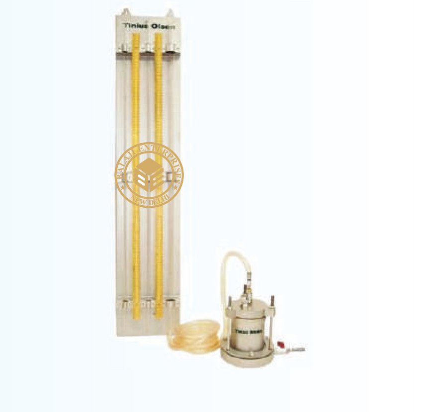
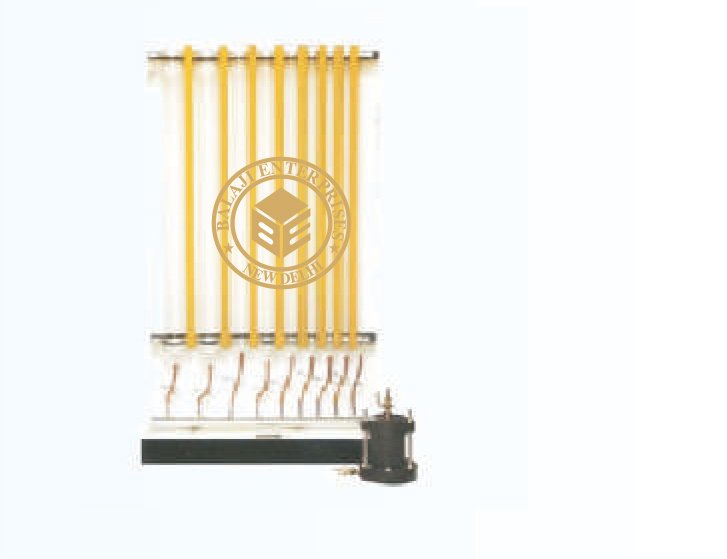
UNIVERSAL PERMEABILITY
MODEL: -GT-031
As Per IS 2720 (Part XBII)- 1966 BS 1377; EN DD ENV 1997-2; ASTM D2434; AASHTO T215
Clays and silts are tested using the technique. Flow of water through the
specimen is observed by monitoring the rate of fall of water in the tube.
It is essential that soils of very low permeability are sealed inside the
cylinder to prevent seepage along the sides of the specimen. Before testing,
the specimen must be completely saturated with water as the presence of
air will restrict the flow of water. Three glass stand pipes a stand with nine
glass tubes of 6mm, 10mm, 20mm, 25mm, 40mm, 50mm, 60mm, 70mm,
75mm, bore tube is provided with over flow arrangement for constant head
tests. The remaining tubes are used for falling head test.
PYCNOMETER
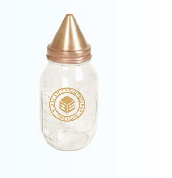
MODEL: -GT-032
As Per IS 2386 (P-III)
Specification :
Specific Gravity is the ratio of the weight in air of a given volume of a
material at a standard temperature to the weight in air of an equal volume
of distilled water at the same stated temperature. The Pycnometer Bottle
can be used to test a wide range of materials from clay to sand and gravel
smaller than 10mm. It consists of 1kg Glass Jar with Brass Cone, Locking
Ring and Rubber Seal.
SOIL TESTING KIT
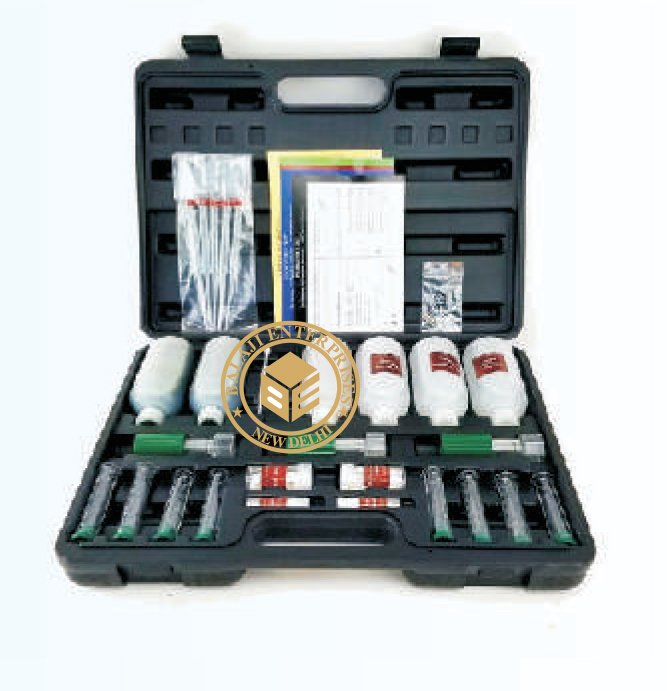
MODEL: -GT-033
A very useful kit to determine on the spot soil pH value. This is a
compact kit easy to carry on site.
Consists of :
12 thick walled test tubes with rubber bungs.
1 tube Cleaning brush.
1 bottle of Barium Sulphate (100gm)
1 bottle of Soil indicator (100gm)
1 bottle of Distilled water (500gm)
1 Spatula.
1 Colour chart, range 4.0 to 8.0 ph in 0.5 ph steps.
Complete with carrying case
WATER TESTING KIT
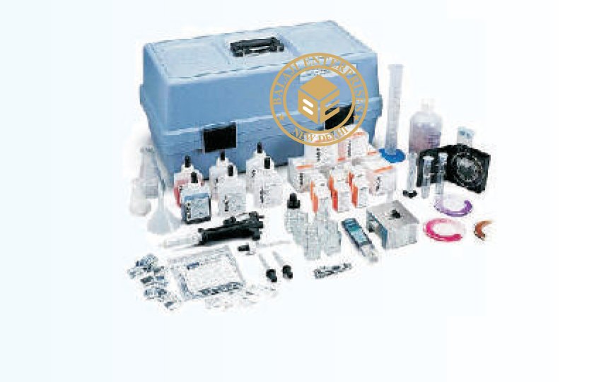
MODEL: -GT-034
I) Acidity Testing Kit
Ii) Chloride Test Kit
Iii) Hardness Test Kit
Iv) Soil Colour Chart
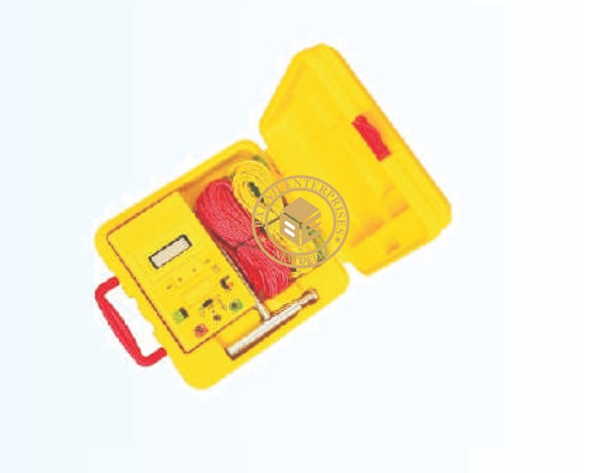
EARTH RESISTIVITY METER
MODEL: -GT-035
ASTM G 57
Capable of measuring earth voltage (V A.C.) 2mA measuring current permits the testing of earth resistance without
tripping earth leakage current circuit breakers in the circuit. Auto power off function. The timer operates auto power
off function. The time operates the “PUSH BUTTON SWITCH” and “TIMER ON BUTTON’ are pressed together.
This will keep the test “NO” for about three to five minutes.
Then auto power off.
Battery operated
Data hold function
Small and light weight
IEC 1010 CAT III 200V
Calibration performed with supplied test leads
Specification:Measurement Ranges
Earth Resistance: 0-20W/0-200W/0-2000W
Earth Voltage: 0-200V AC (40-500Hz)
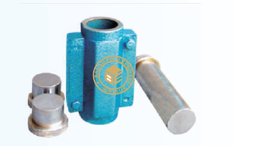
CONSTANT VOLUME MOULD
MODEL: -GT-036
Often in the laboratories it is required to quickly prepare remoulded
soil specimen for Triaxial and Unconfined tests. Constants volume
moulds are used for this purpose, using either dynamic or static
compaction. The moulds are available in different sizes. For specimen
size 38 mm dia x 76 mm long comprises. Split mould 38 mm dia x 126
mm long. End plugs 38 mm dia x 25 mm long pair. Split collar
interchangeable. Ejecting plunger 38 mm dia x 126 mm long.
Accessories split mould 38 mm dia x 76 mm long and Split mould 38 mm dia x 86 mm long.
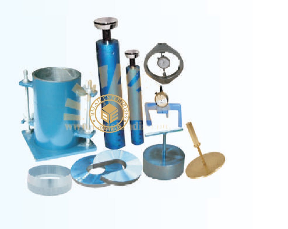
RELATIVE DENSITY TEST
MODEL: -GT-038
IS 2720 (PART XIV), ASTM D 4253 & ASTM D 4254
The equipment is used for the determination of the relative density of
cohesion less free draining soils and meets the essential requirements.
Specification :
The equipment consists one each of: Vibratory table, with a cushioned
steel vibrating decks about 75cm x 75cm. It has a frequency of
approximately 3600 vibratory table, minute under a 11.5kg load.
Amplitude is variable in between 0.65mm in step of 0.05 to 0.25mm,
0.25 to 0.45 mm and 0.45 to 0.65mm. Suitable for operations on 415V,
Three Phase supply. Cylindrical metal unit weight mould, 3000ml.
Capacity.Guide sleeve with clamp assembly. Surcharges base plate for
mould. Handle for surcharge base plate. Surcharge weight. The total
weight together with surcharge base plate and handle is equipment to
140 kg. /sq. cm. For mould. Cylindrical metal unit weight mould 15000
ml. capacity. (Total weight together with the above mould & surcharge
weight is equivalent to 140 kg./sq. cm) dial gauge 0.01mm x 50mm travel.
Extension piece 25mm for dial gauge.
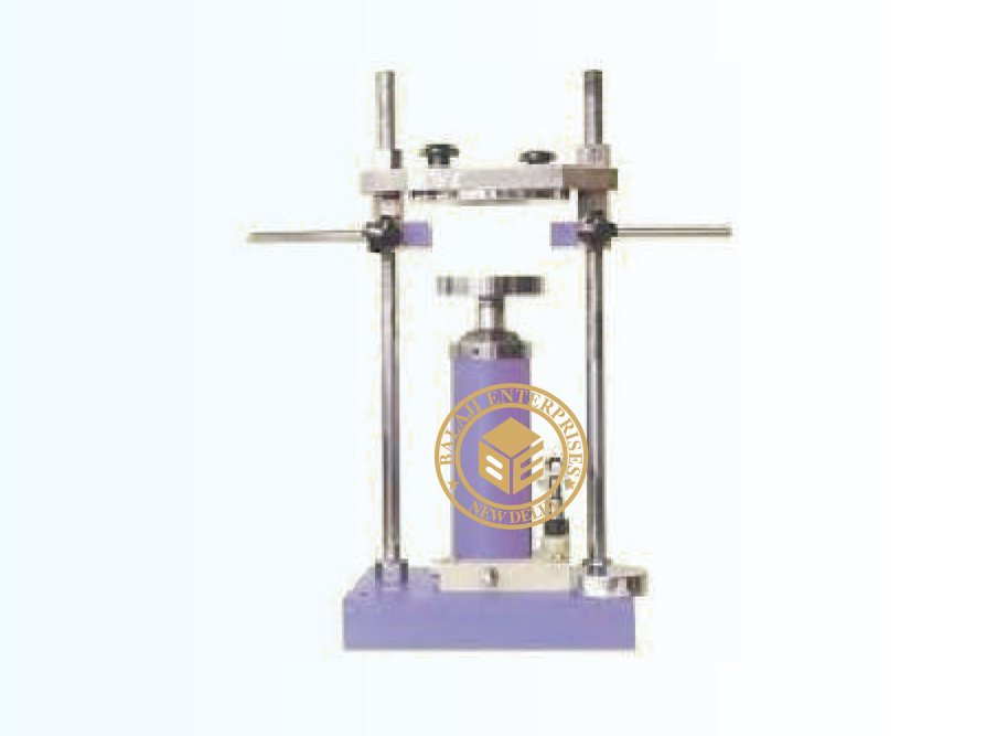
UNIVERSAL EXTRUDES (HYDRAULIC)
MODEL: -GT-039
The extractor frame is used for taking out soil samples compacted or
undisturbed, from 100mm dia and 150mm dia cylinders such as Core
Cutters, Proctor moulds, C.B.R. moulds etc.
Specification:
It consists of a 50Kn capacity hand operated, hydraulic jack mounted
on a suitable frame. Two plungers, one for 4″/100mm dia and the other
of 6″/150mm dia moulds are supplied Height of thrust plate is adjustable.
Set of plungers
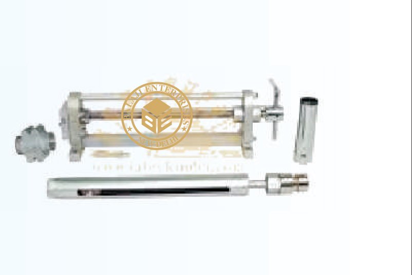
SC MODEL TORQUE COMPENSATED POWER PACK
MODEL: -GT-040
ASTM D 698 , BS 598:107
Designed to extract specimens from almost every type of sampling tube and
mould used in solid engineering laboratory or in the field. It can be mounted
vertically or horizontally as desired. It has an unique feature that three 38mm
dia sample.
Specification:
Comprises of a frame designed for screw jack operation, one each of the
adaptors for 38mm, 75mm, 100mm, 150mm dia meter specimens and a stand
to obtain simultaneously three 38mm diameter samples from one 100mm
diameter sample. The adaptor plate which slides along the slotted support can
be claimed at any desired position by means of locking nuts. Besides this, the
tube or mould can be held in position by raising the tube guides and held in
position with locking screws. The lead screw movement can be stopped at any
predetermined position by tightening the lead screw collar. Plunger adaptor
for 200mm dia samples. Adaptor plate with 200mm dia hole and device to
extract b number 38mm dia samples.
SAMPLING TUBES
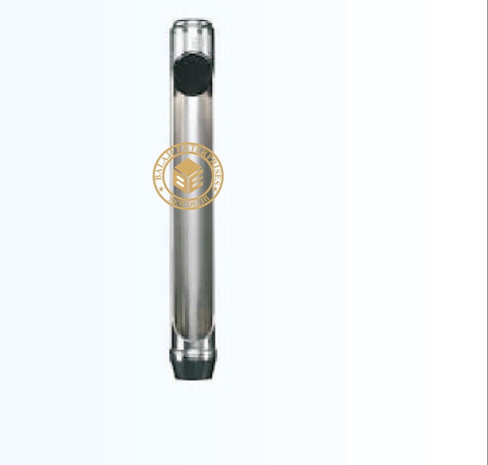
MODEL: -GT-041
For collection undisturbed samples of 38mm dia for triaxial strength and unconfined compressive strength either
straight from the field or from a sample of larger diameter. The wall thickness is maintained approximately 17 per
cent. Both relieved and unrelieved sampling tubes are available. In the relieved type of tube, the internal diameter
is relieved by about 0.5mm (inside clearance 2%) beyond approx. 19mm length from the cutting edge of the tube.
This is most suitable for highly cohesive soils. In the unrelieved type, the internal diameter is uniform through out.
This type is most suitable for soil of low cohesion. These 38mm dia tubes are available in different lengths.
AUGER POSTHOLE TYPE
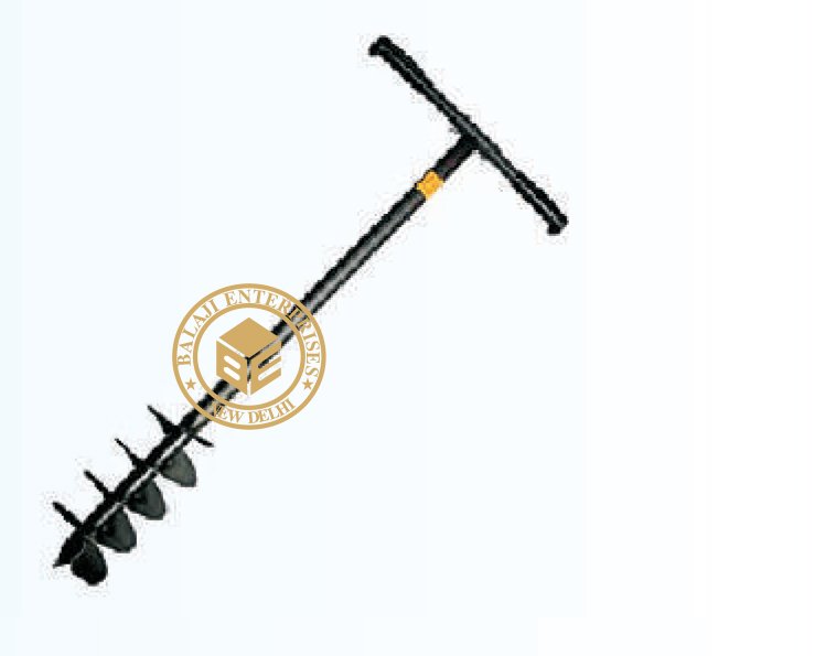
MODEL: -GT-042
Augers are used to collect disturbed soil samples at reasonal depths for
laboratory tests. Augers are available in two types and each in different
sizes. Blade type (posthole type) and helical type (screw type). Each auger
outfit consists one each of auger head, one meter long rod, tee piece and
handle. Depth of excavating can be increased using additional extension rods.
Posthole Type:
(a) 50mm, (b) 75mm (c) 100mm dia (d) 150mm dia
Screw Type: (SL-GT-042.A)
(a) 25mm, (b) 38mm, (c) 50mm, (d) 75mm, (e) 100mm, (f) 150mm, (g) 200mm, (h) 250mm, (i) 300mm dia,
Extra: Extension rod 1 meter length with threading at both ends and couplings, set of two spanners and tee piece.
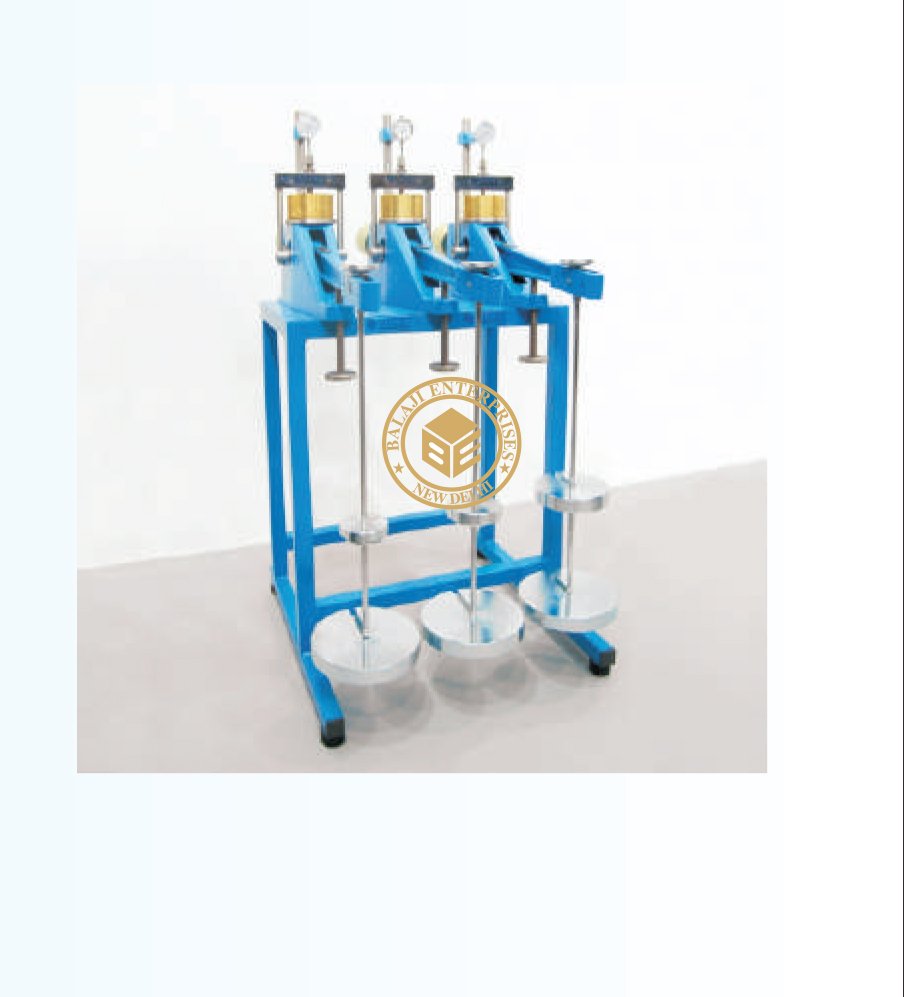
CONSOLIDATION APP. (SINGLE GANG)
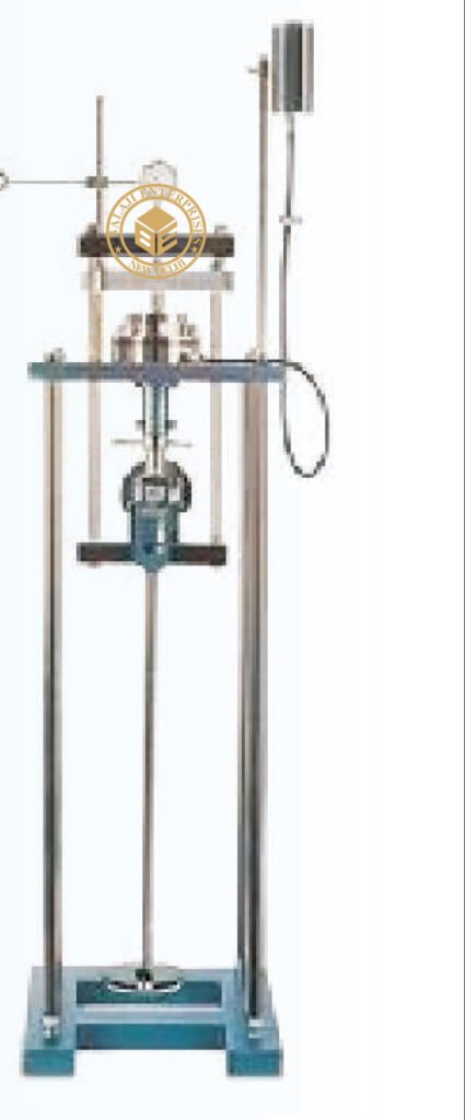
MODEL: -GT-043
IS 2720 (Part XV), IS 12287, BS 1377, ASTM D 2435
Consolidation test is un-dimentional test considered extremely important in
soil mechanics. Sample taken from adjacent areas of a single site show
differential settlement even when tested using same techniques. Soil of
similar strength may show varying consolidation. Samples are very carefully
prepared and vertical settlement of the specimen in saturated or drained
conditions carefully recorded when known load is applied.
SPECIFICATION:
The standard outfit comprises of the following items. Loading unit, maximum
capacity 20kg/cm.sq. Having a loading yoke connected to a lever arm with a
counter balancing adjustment and having a lever ratio of 1:1 the whole assembly
being mounted on a sturdy steel frame stand. The loading unit is so designed
that it can be used for consolidation cells of different diameters as well as
different dia floating ring type consolidation cells. Fixed ring type Consolidometer
(Odeometer) cell assembly for testing 60mm dia x 20mm thick specimen comprising:
Fixed ring for specimens 60mm dia x 20mm thick with guide ring. Top and bottom
porous stones for 60mm dia specimen. Perforated pressure pad, Channeled base
with water inlet and gasket Flanged water jacket, water reservoir with plastic tube
and pinch cock. Set of weights to give a pressure of 10kg/cm.sq. On 60mm dia
specimen, comprising : 7 nos. 0.05 kg/cm .sq., 5nos. 0.1 kg/sq.cm., 6nos. 0.5kg/sq.
cm., and 5 nos. 1.0 kg/sq.cm. Supplied complete as above but without dial gauge.
ACCESSORIES :
Dial gauge 0.002 mm x 10mm. Extension piece, 40 mm long, consolidation test
forms pad of 50 for one dimensional consolidation.
OPTIONAL EXTRAS :
Varying head stand pipe, 50cms. Long with mm. Scale. Fixed ring type of
Consolidometer (Odeometer) cell assembly for 50mm. dia x 20mm thick specimens ,
complete with fixed ring guide ring. Pair of porous stones, perforated pressure pad,
channeled base, gasket and flanged water jacket. Set of weights to give a pressure
of 10kg/sq.cm. on 50cm. dia specimen. Fixed ring type of Consolidometer (Odeometer)
cell assembly for 70mm dia x 20mm thick specimens, complete with accessories as above.
Set of weights to give a pressure of 10 kg/sq.cm. on 70mm dia specimens. Fixed ring
type of consolidometer (odeometer) cell assembly for 100mm dia x 25mm thick specimens,
complete with accessories as above. Set of weights to give a pressure of 10 kg/sq.cm. on
100mm. Dia specimens.
CONSOLIDATION APP. (THREE GANG)
MODEL: -GT-045
IS 2720 (Part XV), IS 12287, BS 1377, ASTM D 2435
Rigidly manufactured from aluminous alloy casting to provide a high
degree of accuracy with any frame distortions under load. The load bridge
group is supported in high accuracy self-aligning seat balls. The beam
provides three loading ratio: 9:1 10:1 11:1 and the beam assembly is
fitted with an adjustable counterbalance weight. It consists of 3
consolidation test assemblies mounted on a single frame. Complete
with 3 sets of Consolidation cell assembly for 60mm dia samples and
three sets of weights each giving 10 kg/sq.cm. On each sample. And
complete with rod holding the weights and coupling block holding the
dial gauge or transducer. Supplied ‘without’: Consolidation cell, Weights,
Dial Gauge (or transducer), holding bench which have to be ordered
separately.
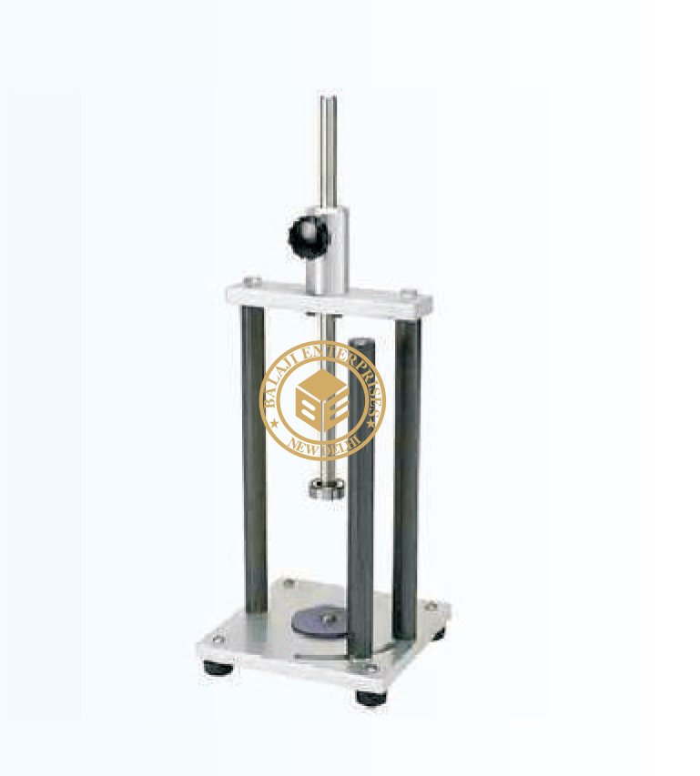
SOIL TRIMMER (HAND OPERATED)
MODEL: -GT-048
ASTM D 698 , BS 598:107
For trimming various diameter specimen for triaxial and unconfined c
ompression tests.
Specification:
The lower specimen grip is mounted on a disc which rotates freely.
The soil sample is mounted on the lower specimen grip and the upper
grip is firmly seated on top of the specimen. The vertical guide can be
adjusted to control the depth of cut. While trimming the lower disc is
rotated by hand. Supplied complete with a wire saw. Trimming knife,
mounted on a support, can be adjusted horizontally as well as vertically
to permit trimming of the specimen to the exact size of the ring. A guide
supplied prevents over cutting. Complete with 38mm, 50mm, 75mm and
100mm dia specimen rings.
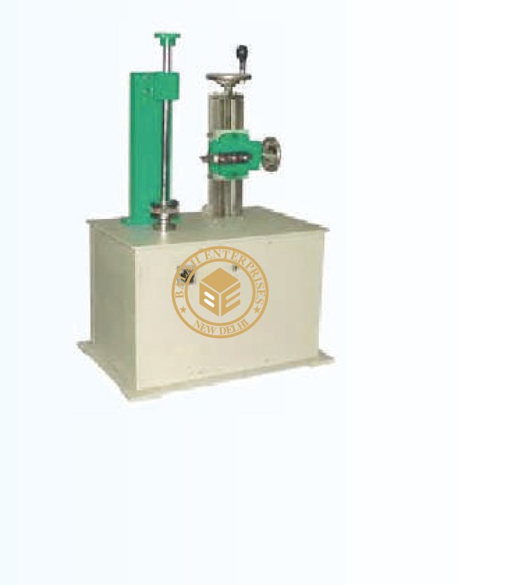
SOIL LATHE BENCH MOUNTING
MODEL: -GT-049
This instrument is used for preparing soil samples for various tests like
Triaxial Test, Unconfined Compression Test etc. Soil lathe consist of a
cabinet enclosing motor and gear system which rotates a disk at 24 R.P.M.
this disc adopts gripper plate of various size. An up right has an adjustable
holder and takes upper gripper plates of different diameters. Arrangement
is provided to control height and depth of cutting tool through a lead screw
which has speeds 0.8mm/min. And 1.6mm/min. Supplied complete with
gripper plate pairs for 38mm, 50mm, 75mm, and 100mm dia specimens.
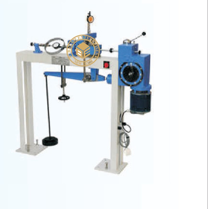
DIRECT SHEAR APPARATUS (MANUALLY)
MODEL: -GT-050
Information of Shear values plays an important role the design of sub-structures in determining bearing capacity of
soils, design of retaining walls, instability calculation earth slopes etc. Various Shear Apparatus are available and
Direct Shear Apparatus is one of them. In Direct Shear test specimen contained in a box is subjected to a constant
normal load and increasing horizontal load is applied to the upper section of the specimen. Shear force and load are
directly measured.
AS PER IS: 2720 (Part-VIII), ASTM D-3080
For determination of the direct shear strength of soils on specimen size 60 mm x 60 mm x 25 mm.
Specification: The apparatus comprises of the following:
Loading Unit:
Supplied with load yoke with direct and lever system for applying load.
Normal stress capacity 8kg/sq.cm. Load is applied either directly of
through a counter balanced detachable lever. Provision is made for
load to be applied either through a steel ball recessed in the loading
pad or direct through a boss on the pre calibrated loading yoke. The
loading unit is provided with V strips and roller strips for frictionless
movement of shear box housing.
Shear Box Assembly:
Comprising Direct Shear box in two halves for a square specimen
size 60 x 60 x 25 mm one pair of plain gripper plates, one pair or
perforated gripper plates, one pair or porous stones, one top loading
pad. Shear box housing: Accommodates the Direct Shear Box assembly.
Complete with two ball roller strips.
Specimen Cutter:
For cutting 60 x 60 x 25 mm specimen from larger samples. Set of weights
to give a normal stress of 3 kg/sq.cm.
through lever as follows:
To give kg/cm sq. – Qty.
0.05 – 4 Nos.
0.1 – 1No.
0.2 – 1No.
0.5 – 3Nos.
1..0 – 1No.
Complete set as above but without proving ring.
Nett weight 140Kg.
Essential Accessories:
High sensitivity compression ring cap 200 kg one consolidation dial gauge 0.01 mm x 25 mm and one strain dial gauge
0.01 mm x 25 mm and one strain dial gauge 0.01 mm x 25 mm.
Optional extras:
Additional set of weights to give a normal stress of 5 kg/cm2 Soil Sampler for 60 mm x 60mm specimen and test from
pad of 50. Spares:
Porous stone for 60 mm x 60 mm size sample available in pairs
CBR APPARATUS MANUALLY OPERATED
MODEL: SL-GT-055
As Per IS 2720 Part (XXXIX) ASTM D-3080, Bs1370
An automatic system enables performing of Direct Shear and Residual
Shear tests through a total computer control. It is a tablemounted model
and has stepper motors controlling shearing load. Stress levels can be
maintained with in the limits of +0.5% through set of weights. Vertical
and horizontal displacements and shearing load are all displayed in their
respective engineering units on LCD display. Board specification of the
unit are:- RS 232 output for connection to PC, Display of both speed and
displacement with 0.0000 mm resolution, Shear speed between 0.00001 to
9.99999 mm/minute
Max shear effort:
5000 N possible on the whole speed range Possibility of direct vertical load,
or with a lever arm ratio 10:1
Max vertical direct load:
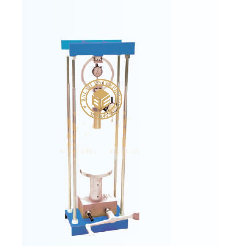
500N; with lever arm: 5500N Display and pilot lamps to signal any bad functioning and alarms Box group mounted on
ball track with high qualit antifriction system Read value results are immediate and of extreme accuracy Extremely easy
and practical use, not requiring qualified staff. Shear box, hollow punch and tamper are not included in the standard
supply and have to be ordered separately Power supply: 230 V A.C. Single Phase 50Hz
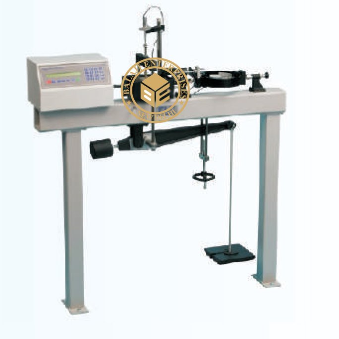
DIGITAL DIRECT SHEAR TEST APPARATUS
MODEL: SL-GT-055
As Per IS 2720 Part (XXXIX) ASTM D-3080, Bs1370
An automatic system enables performing of Direct Shear and Residual
Shear tests through a total computer control. It is a tablemounted model
and has stepper motors controlling shearing load. Stress levels can be
maintained with in the limits of +0.5% through set of weights. Vertical
and horizontal displacements and shearing load are all displayed in their
respective engineering units on LCD display. Board specification of the
unit are:- RS 232 output for connection to PC, Display of both speed and
displacement with 0.0000 mm resolution, Shear speed between 0.00001 to
9.99999 mm/minute
Max shear effort:
5000 N possible on the whole speed range Possibility of direct vertical load,
or with a lever arm ratio 10:1
Max vertical direct load:
500N; with lever arm: 5500N Display and pilot lamps to signal any bad functioning and alarms Box group mounted on
ball track with high qualit antifriction system Read value results are immediate and of extreme accuracy Extremely easy
and practical use, not requiring qualified staff. Shear box, hollow punch and tamper are not included in the standard
supply and have to be ordered separately Power supply: 230 V A.C. Single Phase 50Hz
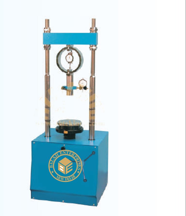
CBR APPARATUS MANUALLY OPERATED
MODEL: -GT-056
California Bearing Ratio Test (CBR)
The C.B.R. Method is used for finding the relative bearing ratio and
expansion characteristics of soil of base, sub-base and sub-grade for
the design of roads, pavements and runways.
Test can be made on all types of soils including sand, gravel, crushed
stone etc. (Passing through 20mm IS sieve) C.B.R. test is used extensively
for selection of materials and control of sub-grades. The procedure of test
is very simple. A 50mm dia. penetration piston is forced in the test soil
and loads required for the penetration to penetrate different depths are
recorded by means of a proving ring fixed to the penetration piston assembly
and a dial gauge. Both Laboratory C.B.R and field C.B.R apparatus are available.
AS PER IS: 2270 (PART-XVI)
California Bearing Ratio Apparatus is made both for laboratory and field use. CBR test is to evaluate the bearing capacity
of soil for the flexible pavement design. It is extensively used for the selection of mater ials and cont rol of subgrades. The
potent ial expansion/consolidation of the specimen is also measured before each test, under known surcharge weights.
This apparatus comprises of :
A hand operated load frame 50kN capacity, A mould of 150 mm. I.D. x 175 mm. high with clamping lugs complete with
extension collar and perforated base plate made of gun metal. A cutting collar to fit mould body. A penetration piston
assembly of 50 mm. diameter and a bracket for the dial gauge. A perforated swell plate of 148 mm. diameter with an
adjustable stem and lock nut. A circular spacing disc of 148 mm. diameter x 47.7 mm. high complete with a removable
`T’ handle. A metal tripod for the dial gauge.
Surcharge weight :
annular _ 2.5 kg., 147 mm. diameter. Surcharge weight : slotted _ 2.5 kg., 147 mm. diameter.

CBR ACCESSORIES
MODEL: -GT-056
CBR Essential :
– Proving ring 10 kN capacity.
– Dial gauge 0.01 mm. x 25 mm. travel.
Spares:
– Rammer 2.6 kg & 4.89 kg.
– CBR mould complete with extension collar and perforated base plate
– Perforated swell plate with adjustable stem and lock nut
– Solid base plate
– Cutting collar
– Penetration piston assembly
– Metal tripod for dial gauge
– Circular spacer disc
– Surcharge weight (Annular) 2.5 kg
– Surcharge weight (Slotted) 2.5 kg

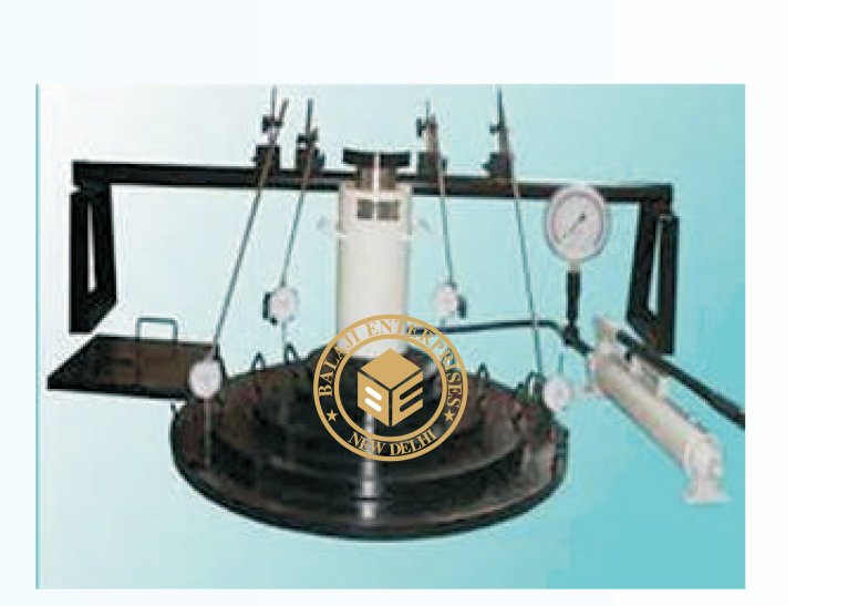
CBR TEST APPARATUS MOTORIZED
MODEL: -GT-057
IS : 9669, IS : 2720 (Part XVI)
It is used in large road construction projects has increased considerably
in recent years. This apparatus, mounted on a rolled steel joint cantilevered
from the back of the truck or fitted to the underside of a mobile frame, can
be used to determine the bearing capacity of soils quickly and efficiency.
This method of testing in-situ, using piston penetration, is useful for
determining the load carrying capacity in the field, when the in -place density
and water contents are such that the degree of saturation is 80% or greater.
When the material is coarse grained and cohesionless so that it is not affected
b changes in the water content and when the material has been inplace. Similar
to above but supplied with bench mounting type 5000kgf. Capacity load frame
motorized, in place of load frame hand operated. The lead screw of the load
frame has a single constant rate of travel of 1.25mm/minute.
Dial Gauge 2 in. travel & 0.001 in division for CBR penetration measurement,
having provision for increasing the dial gaugeplunger length .Proving ring ,
50 kN (5,000kgf) capacity x 0.5. kN/Div sensitivity/ readability, one with 25 kN capacity x 0.04 kN / div sensitivity /
readability and one with 10 kN capacity x 0.01 kN / div sensitivity / readability.
Note: Proving Rings of other capacities are also available.
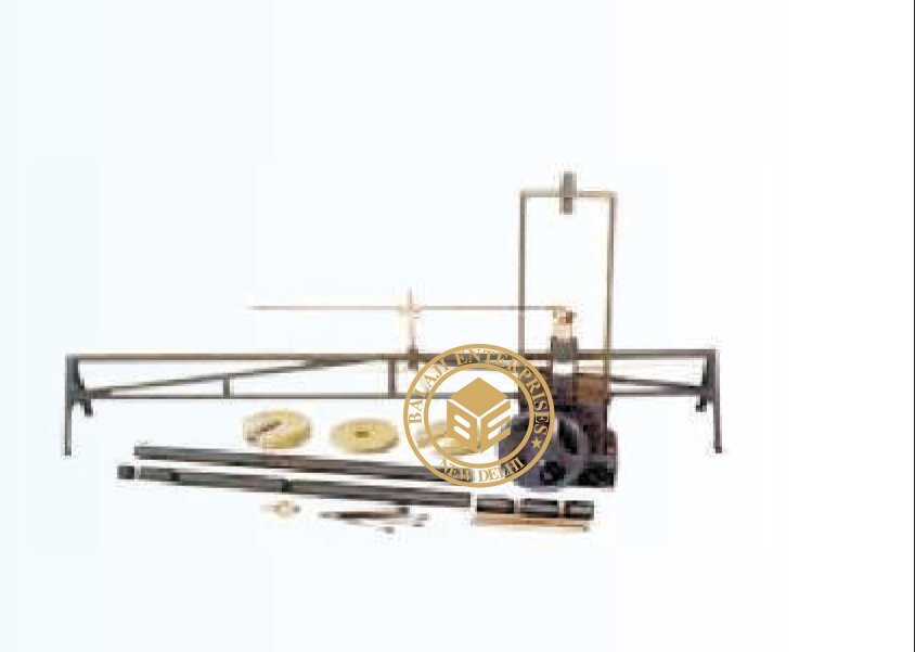
CBR TEST APPARATUS (FIELD TYPE)
MODEL: -GT-058
IS 2720 (PART XXXI) 1969.
In recent years it has become important to know C.B.R. values in situ.
It is useful in determining the load carrying capacity in the field when
in place density and water contents are such that the degree of saturation
is 80% of greater, when material is cohesionless and coarse grained, such
that it is not effective by changes in water contents and when the material
has been in place for considerable the loading is effected by means of a
mechanical load frames which can be fixed to the under side of a truck.
Specification:
Mechanical screw loading jack, 10,000 kg. Capacity with u-bracket and swivel head. Penetration piston, 50mm dia.
Threaded at the upper end. Extension rods consisting of 2 lengths 5 cm. g lengths 10cm. 1 length 30 cm., 1 length 50 cm.
and 1 length 100 cm. used as spacers between the proving ring and penetration piston. The lengths are machined from
steel tubing. Connector set, has eight connectors for coupling the penetration piston and proving ring assembly either
directly or through extension pieces. Dial gauge support of seamless pipe constructions. It stands 30 cm high and 45 cm.
Wide at the base. Provided with a quick release screw type clamp capable of sliding and locking anywhere along 2 meter
length of the bridge. Supplied with annular metal weight 5 kg., 250mm dia with 53 mm dia central hole, slotted metal
weight 5 kg., 215mm to 250mm dia with 53 dia slot 2 nos.
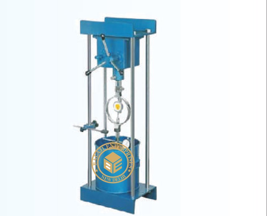
SWELL TEST APPARATUS
MODEL: -GT-059
It is designed to determine the swelling pressure developed by soil
specimens moulded to desired densities at known moisture contents,
when soaked in water. The load applied to restrain the swelling is
transferred on to a load measuring proving ring through a perforated
swell plate and a load transfer bar. The proving ring is attached to
the lead screw of hand operated load frame. A soaking tank is provided
for saturating the specimen and the base of the mould provided has
channels and radial grooves with connecting holes.
Load Frame, Hand Operated, Capacity 50 KN (5,000 kgf), Mould,
100mm dia x 127.3mm height (1,000ml volume) with, base plate and
collar., Proving Ring, with integral boss, high sensitivity 2.5KN (250 Kgf) capacity, Perforated swell plate, 100mm dia
x 16mm thickDial Gauge , 25mm travel, 0.01mm least count Lid & receiver in G.I. frame for 300mm dia x 450mm dia
sieves, Spencer, 100mm dia x 12.7mm thick, Pair of Porous stones, 100mm dia x 12.7mm thick, Load Transfer Bar,
Steel Ball Soaking Tank, 250mm dia x 210mm high.
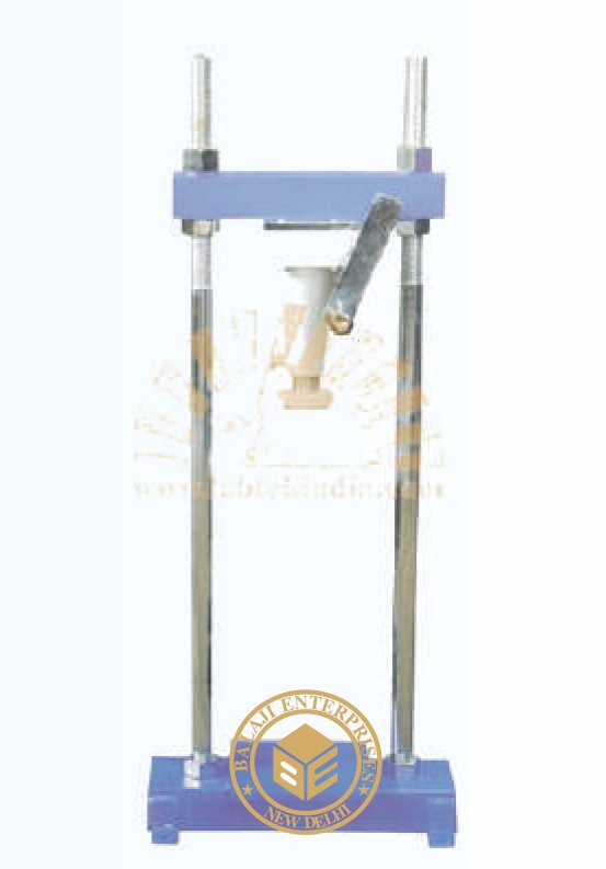
UNCONFINED COMPRESSION TESTER PROVING RING TYPE (HAND OPERATED)
MODEL: -GT-059
It is designed to determine the swelling pressure developed by soil
specimens moulded to desired densities at known moisture contents,
when soaked in water. The load applied to restrain the swelling is
transferred on to a load measuring proving ring through a perforated
swell plate and a load transfer bar. The proving ring is attached to
the lead screw of hand operated load frame. A soaking tank is provided
for saturating the specimen and the base of the mould provided has
channels and radial grooves with connecting holes.
Load Frame, Hand Operated, Capacity 50 KN (5,000 kgf), Mould,
100mm dia x 127.3mm height (1,000ml volume) with, base plate and
collar., Proving Ring, with integral boss, high sensitivity 2.5KN (250
Kgf) capacity, Perforated swell plate, 100mm dia x 16mm thickDial
Gauge , 25mm travel, 0.01mm least count Lid & receiver in G.I. frame
for 300mm dia x 450mm dia sieves, Spencer, 100mm dia x 12.7mm thick,
Pair of Porous stones, 100mm dia x 12.7mm thick, Load Transfer Bar,
Steel Ball Soaking Tank, 250mm dia x 210mm high.
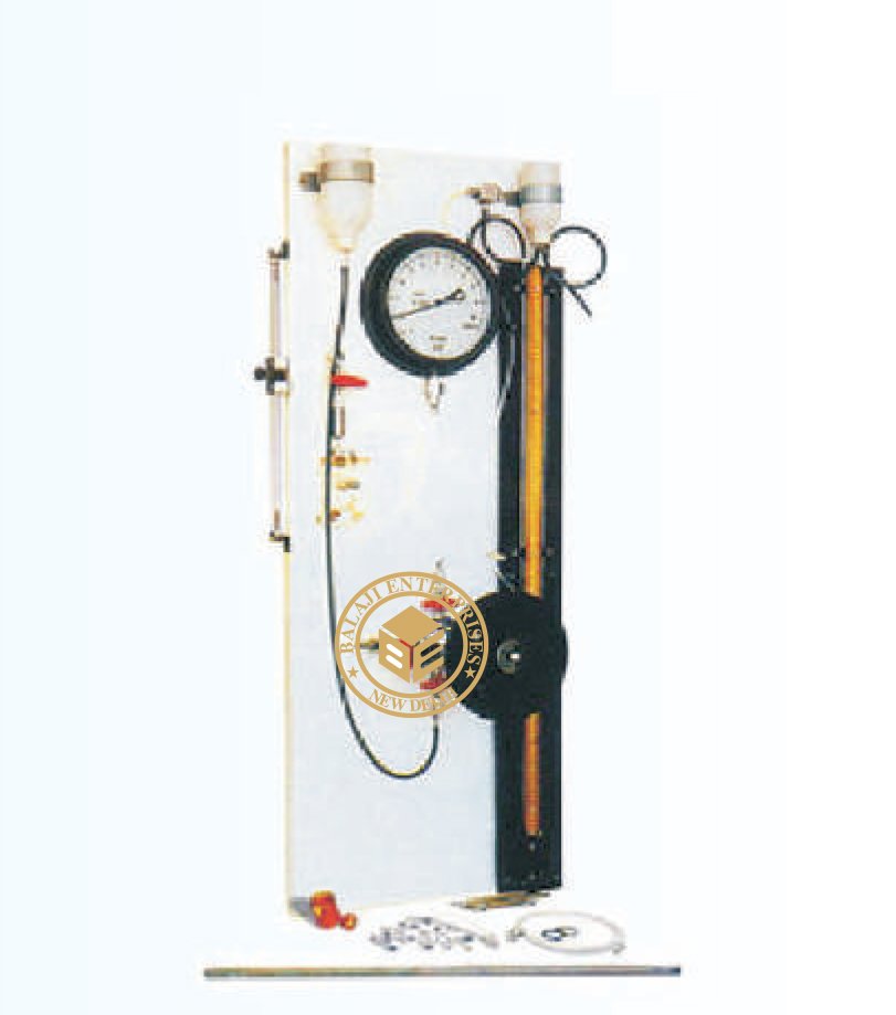
PORE PRESSURE APPARATUS 10KG/CM2
MODEL: -GT-062
This apparatus is used for measuring pore water pressure and pore air
pressure in soils. This is as per the principals outlined in the book
” measurement of soil properties in triaxial tests” by A.W. BISHOP
and D.J. HENKEL. This is used as an accessories for triaxial test apparatus.
SPECIFICATION :
The apparatus consists of a panel for wall mounting on which are fitted
1.0 to 10kg/cm sq x 0.1kg cm. sq. a pressure gauge, bourdon tube type
15 cm dia.
MANOMETER :
Glass u-tube manometer for measuring low positive pore pressures negative
pore measures and checking zero error of pressure gauge. It is provided
with a mercury trap (mercury supplied at extra cost.) Null indicator made
out of clear transparent Perspex with mercury trap and cursor to indicate
the mercury level.
BURETTE :
50ml burette for measuring the volume change in the soil specimen. Pressure pump fitted with four sleeve packed valves,
operated by means of a hand wheel on the end of the piston rod which is threaded through the pump cap and gives a
smooth, fine adjustment of pressure. Copper coil and water reservoir is fitted on board with complete stand assembly.
The unit is tested against leaks up to 10kg/cm sq.
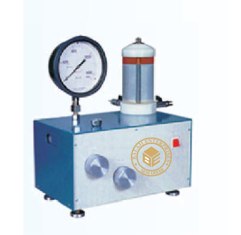
DEAD WEIGHT TYPE OIL AND WATER CONSTANT PRESSURE SYSTEM
MODEL: -GT-064
BS 812 This device is used to maintain cell pressure constant for a long
duration and the system can be used in place of conventional constant
pressure system using mercury pots where certain minimum heights are
required. Problems like de-airation of pump, leakage of mercury etc. is
eliminated in this system . This unit is smaller in volume and can be used
in mobile laboratory also. This can maintain pressure in the cell upto
20kg/cm sq. Pressure is maintained constant in the system by a balancing
calibrated weights on a spindle against a column of oil, operating under
constant feed back.
CONSTRUCTION :
The system consists of an oil pump continuously driven by an electric motor
during the test period. The internal components are housed in a strong compact
housing. The piston on which weights are kept rotates with minimum friction.
A transparent oil water vessel is provided to transmit pressure to the cell. A hand pump provided facilitates priming
and to maintain constant pressure during power failure.
SPECIFICATION :
Range 0-20 bar(0-20kg/cm2 ), Steps of pressure 0.5bar (0.5kg/cm2 ), Accuracy + 0.5%, Electric supply 230 V,
Single Phase, 50 Hz, A.C. supply., Supplied complete with pressure gauge, flow valves, connecting pressure,
hose and set of weights to give maximum pressure of 20 bar (20 kg/cm2)
LOAD FRAME HAND OPERATED
MODEL: -GT-065
Triaxial Setup
Triaxial setup has different main components. These components are
selected to complete the setup. In the following pages specifications are
given of each components. Main component requirement for this test are:
I) Load Frame
ii) Triaxial Cell
iii) Lateral Pressure Assembly
iv) Measuring Unit
Load Frames
Load frame is essential equipment for carrying out Unconfined Compression,
CBR and Triaxial Shear Tests. Since very slow rates of strains are required
for Triaxial Shear Tests LabTek load frame are made to suit the same.
A suitable frame can be selected from a wide range of LabTek series of Load frames depending upon the type of test
and the size of sample. Each load frame is provided with a standard proving ring adaptor having ½” BSF male threads
to suit LabTek range.
Load Frame, Hand operated, 50 kN
The load frame is designed for a maximum load of 5000 kgf. It consists of a screw jack mounted in a reversible
channel frame, which can be used for loading from top to bottom and vice versa

LOAD FRAME, MOTORIZED, 50 KN (1 SPEED)
MODEL: -GT-066
Triaxial Setup
Triaxial setup has different main components. These components
are selected to complete the setup. In the following pages specifications
are given of each components. Main component requirement for this test are:
I) Load Frame
ii) Triaxial Cell
iii) Lateral Pressure Assembly
iv) Measuring Unit
Load Frames
Load frame is essential equipment for carrying out Unconfined Compression,
CBR and Triaxial Shear Tests. Since very slow rates of strains are required
for Triaxial Shear Tests LabTek load frame are made to suit the same.
A suitable frame can be selected from a wide range of LabTek series of Load
frames depending upon the type of test and the size of sample. Each load frame
is provided with a standard proving ring adaptor having ½” BSF male threads
to suit LabTek range.
Load Frame, Motorized, 50 kN (1 Speed)
It is a single speed load frame designed for 1.25 mm/min strain rate. It
can accommodate Triaxial cells up to 100mm diameter specimen.
Loading capacity is 50kN.Operates on 220V,50Hz supply
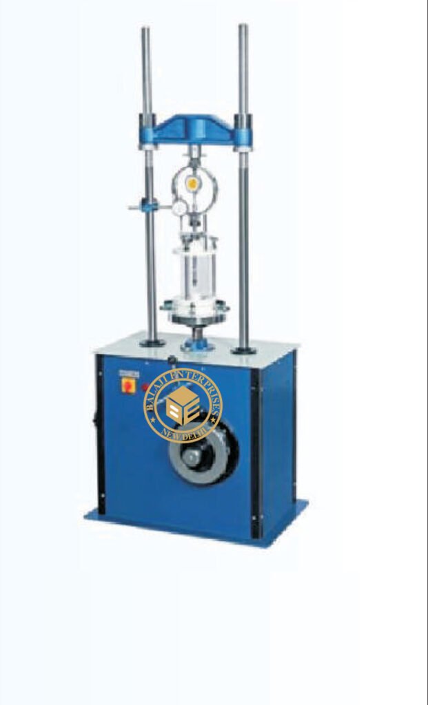
DIGITAL LOAD FRAME
MODEL: -GT-070
It is an advanced version of mechanical load frames. In this load
frame, rate of strain is controlled through combination of
electronics and micro stepper motor. The unit operates on 220Volts
50Hz single phase supply.
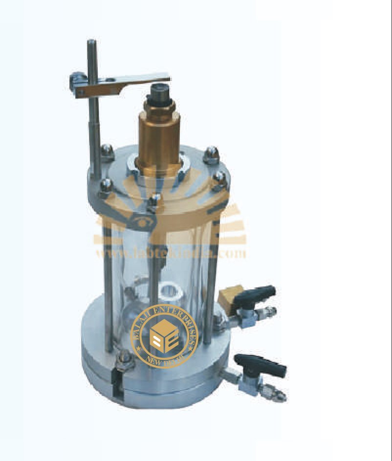
TRIAXIAL CELLS
MODEL: -GT-071
IS 2720 (PART XII)
The cell is useful for testing 38mm dia x 76mm high soil specimen.
Transparent Perspex chamber with anvil and loading plunger, the
cell is easily opened by releasing four nuts of the tie rods. It is leak
proof up to 10kg/cm.sq. Fluid pressure. An oil plug which can also
be used as an air vent is provided for introducing a thin layer of oil
over water. This provides effective sealing at the plunger for long
duration tests. The cell is fitted with four sleeve packed valves of no
volume change type on the base.
These valves are used for cell pressure, pore water pressure, drainage
or back pressure. The loading plunger of the cell has dial gauge rest.
Loading pad made of Perspex for 38mm dia specimens. Pair of plain
discs made of Perspex 38mm dia 6mm thick. Pair of porous stones
38mm dia specimen. Split sand former for 38mm dia specimen. Sheath
stretcher for 38mm dia specimen. One dozen rubber sheaths for 38mm
dia samples. For synthetic rubber ‘o’ rings for 38mm dia specimen.
One plastic drainage tube.
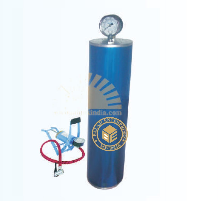
LATERAL PRESSURE ASSEMBLY
Lateral Pressure Assembly 10kg/cm2
It is designed for application of cell pressure upto 10kg/cm on a triaxial
specimen in the triaxial cell. The unit is mostly used in routine tests which
last for about 10 to 15 minutes wherein the variations of cell pressure can
be tolerated.
Specification:
The apparatus consists of a pressure chamber which has a flanged top 2
cap fitted with a 10 kg/cm . Pressure gauge and a valve for pumping in air.
Water inlet and drain cock are fitted to the chamber. 2 The foot pump
supplied easily develops a pressure of 10 kg/cm2 Complete with connecting
pressure hose.
Lateral Pressure Assembly 20kg/cm2
Same as above but suitable to develop pressure upto 20kg/cm fitted with suitable pressure gauge.
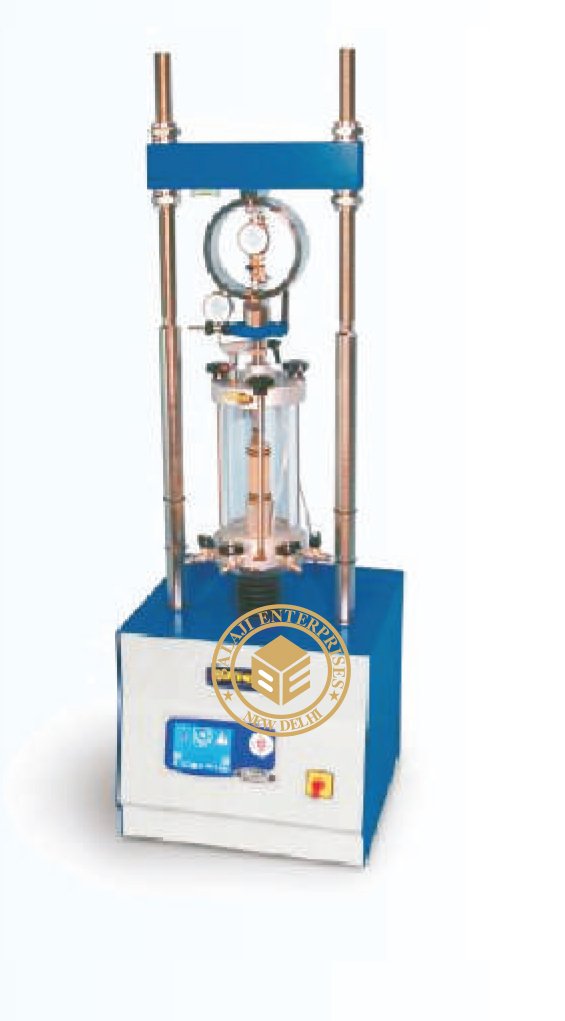
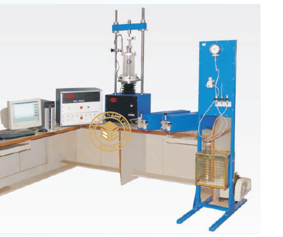
DIGITAL TRIAXIAL SHEAR TEST APPARATUS
MODEL: -GT-072
IS-2720 (Part-XII) and BS-1377.
LabTek Digital Triaxal is totally automated stress path system for soils and conforms to the test requirements of All the
modules namely load frame, confining pressure, back pressure, pore pressure or volume change are totally controlled by
the dedicated computer. Once the specimen is assembled in the triaxial cell, required parameters like strain rate,
confining pressure and back pressure are programmed through the computer. Controlling and data acquisition is
supported by window based software. It can perform tests under the following conditions:
1. Shear in UC, UU, CU, CU & CD
2. Stress path triaxial test
3. K0 consolidation and swelling test (optional) Detailed
specifications of the individual modules are given as under:
1. Load Frame
It is a two-pillar type load frame that can accommodate triaxial
cell up to 100mm dia specimen. Rate of strain is precisely controlled
through micro stepper motor of fractional horsepower operating at
220volts, 50 Hz single phase supply (other voltages optional).
i) Capacity of the load frame : 50 kN
ii) Rate of strain: 0.00001 – 9.9999 mm/min
iii) Travel : 100 mm Limit switches and L.E.D are incorporated in the
hardware to arrest the travel limits and also to indicate the direction of movement (up/down).
2. Triaxial Cells
Selection could be made from wide range of triaxial cells, they are light weight cells. Transfer bar (loading ram) passes
through linear bearing making it almost friction free. Base has four no-volume change valves one each for back pressure/
pore pressure, confining pressure and top drainage.
Specimen size : 38/50mm diameter
Accessories: As standard the following accessories are supplied along with the
Triaxial Cell: -Sheath Stretcher, Porous Stones, Plain Discs, Top drainage Cap, Rubber membranes (Pack of 10) and
‘O’- Rings.
(Universal Triaxial cells)
Confining Pressure : 1700 kPa
Specimen size:
38 mm dia x 76 mm high, 50 mm dia x 100 mm high, 75 mm dia x 150 mm high, 100 mm dia x 200 mm high
Standard accessories include, Sheath Stretchers, Rubber membranes (Pack of 10), ‘O’- Rings, Porous stones,
plain discs and top caps.
3. Pressure Controller For Confining Pressure
A micro stepper motor runs pressure controller and the controlling is done through computer. Sensitivity of controlling
is within +10 kPa. Volume displacement in one filling is approximately 300 c.c. Sensing of pressure is through sensitive
pressure sensor.
Pressure range : 1700 kPa
Volume capacity : 300 cc
Controlling accuracy : +10 kPa
4. Pressure Controller For Back Pressure with volume change
Pressure range : 1700 kPa
Volume : 300 cc
Sensitivity : +10 kPa
Volume change
Measurement : 300*0.01cc
5. Sensors
Force Sensor Load cell capacity: 10kN
Pressure Sensor Range : 2000 kPa
Displacement Sensor Range : + 20mm
6. Computer
Pentium IV – 3.0Ghz or higher 512MB RAM, 80 GB HDD, CD writer, Standard Keyboard , Scroll Mouse,
Color Monitor, Deskjet/ Laser Printer (if requred)
Note : Up graded system will be supplied.
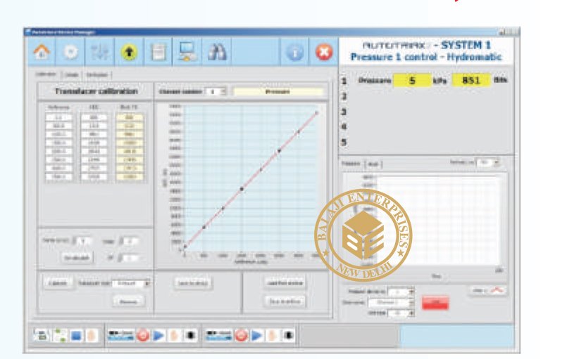
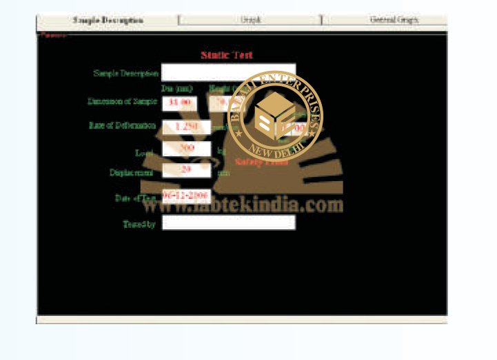
SOFTWARE FOR TRIAXIAL TEST (ALL ELECTRONIC MODELS)
1). Does all calculations of UC, UU, CU,CU & CD triaxial tests
2). Has option for manual as well as automatic recording of data
3). Displays the following plots (Graphical)
a). Plots consolidation curve & evaluates t100 and calculates strain rate
depending Upon the drainage condition in CD & CU
b). Stress – strain curves after every test
c). Plots pore water pressure and A – factor (for CU) and volumetric strain
(for CD) vs. axia Effective stress ratio vs. axial strain
d). p-q plot
e). Mohr stress circles & envelope giving C & in terms of effective stress.
DIGITAL TRIAXIAL ACCESSORES
OPTIONAL ACCESSORIES.
1 Lateral extensometer (submersible type).It is a ring type extensometer
which exerts a bare nominal pressure on the specimen. Extension/
contraction is measured by submersible L.V.D.T and the parameter
is directly displayed on the monitor in engineering units. *
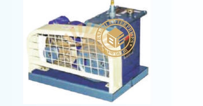
STATIC CONE PENETROMETER CAPACITY 100KN (10,000KGF) (ENGINE DRIVEN)
MODEL: BE-GT-074
IS 4968 (PART III)
For reaching greater depths and to facilitate easy and constant rate of penetration 1 to 2.5cm/sec of the cone this
engine-driven Static Cone Penetrometer of 100 KN (10,000 Kgf) capacity is preferable. The equipment consists of a
hydraulic pump driven by a Diesel Engine. The whole system is mounted on a tow able trolley fitted with pneumatic
wheels. The pumping unit and ram are connected by means of flexible pipes through a direction control valve. The
hydraulic ram moves on a two pillar stand mounted on a trolley.
Complete With The Following :
01). Penetration Cone, steel 60 cone angle, 10cm2 base area, with friction jacket One
02). Mantle Tube, 36mm uniform OD with sounding Rod working length 1 m Thirty
03). Load Measuring Head, with Automatic cut-off valve, and oil can without pressure gauges. One
04). Pressure Gauge, 0-600 x 5 kg/cm One
05). Pressure Gauge, 0 100 x 1kg/cm One
06). Trusses Two
07). Screw Anchor 45 cm Six
08). Screw Anchor 30 cm Six
09). Screw Anchor 20 cm Six
10). Screw Anchor Rod with cone Six
11). Driving handle for Screw Anchor One
12). Extension Pipe for Handle Four
13). Clamping Screw with Nuts Six
14). Extractor Tube with Connector One
15). Tarpaulin Cover One

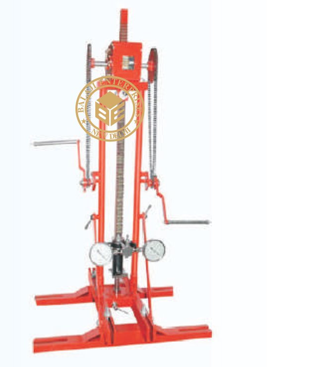
STATIC CONE PENETROMETER, 30KN (300KGF) CAPACITY, HAND OPERATED
MODEL: -GT-073
IS 4968 (Part III)
Static cone penetration test is internationally recognized as a standard field test to collect data about bearing capacity and
frictional resistance of soil.Static C one Test is unsatiable e for gravelly soils. The Static Cone resistance is correlated with
the ‘N’ value as obtained from standard penetration test, thus in cr easing the utility of the test.
The drive is by means of a rack and pinion manually through a gearing arrangement.
The gear box and pinion are fixed on two handles, sprockets and chain arrangement.
The movement of the rack is guided by a bracket ( attached to the rack) and two pillars.
The penetration resistance i.e. the pressure is indicated on hydraulic gauges through a
hydraulic measuring head. Two pressure gauges of 15cm dia dial and 2 capacities
0-160kg/cm are provided. An automatic cut-off valve, to protect the low capacity gauge
from being overloaded is provided. The 2 valve can be adjusted and locked at desirable
values between 20 to 60cm . A provision is made to anchor the unit to the ground (with
the help of four anchors supplied with the unit) and there is a provision for lateral 2
movement of the unit so that subsequent tests could be performed without shifting the
entire anchorage. A 10cm penetration cone with friction jacket is provided along with
fifteen mantle tubes (non-uniform having an effective length of 1 m each with sounding
rods for finding out the cone (point) resistance or jacket friction.
It consists of :
01) Penetration Cone, steel 60 angle 10cm base area with friction jacket One
02) Mantle Tube, non-uniform , 36mm OD at the two ends and reduced dia in between with sounding rod working
length 1mfifteen.
03) Load Measuring Head, with Automatic Cut off valve and Oil Can, without Pressure Gauge One
04) Pressure Gauge, 0-60kg/cm One
05) 2 Pressure Gauge, 0-160kg/cm One
06) Screw Anchor , with Bolt Four
07) Anchor Driving Handle One
08) T-Rod One
09) Spanner One
10) Extension Pipe 0.5m long for Anchor Driving Handle Four
Note : Uniform dia mantle tubes can be ordered at extra cost.
Optional Extra
Mantle Tube, 36mm uniform OD with Sounding Rod, working length 1 m
SPLIT SPOON SAMPLER
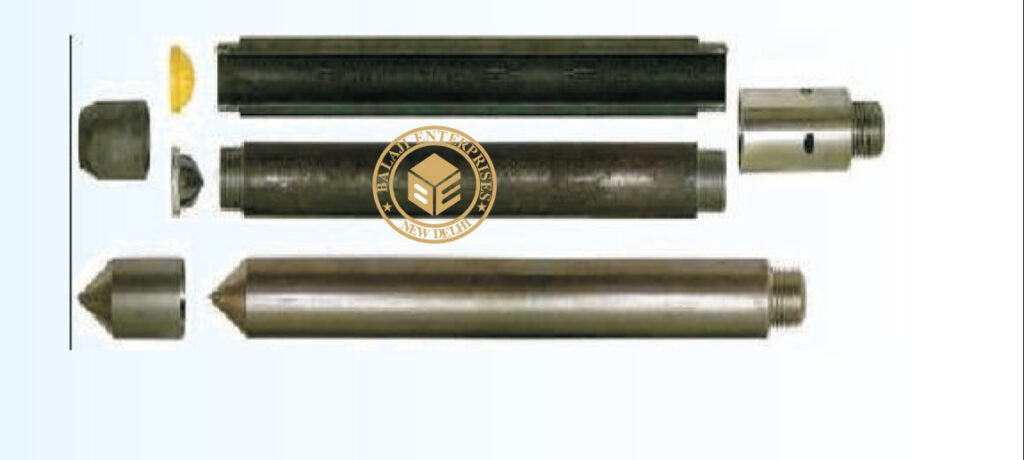
MODEL: -GT-075
IS 2131-1963, IS 9640-1980
This is used for standard penetration test for determining penetration resistance (N valve) of soil which can be related to
unconfined compressive strength. Penetration resistance (N value) of soil is determined by giving a number of blows with
a 65 kgs weight falling through a given distance of 75cm required to penetrate the assembly to a depth of 30 cm when
properly seated on the ground. The sampler is made from a steel tube split length wise & held together by a head fitted
with a ball check valve & a hardened steel shoe in size cutting edge of 35mm dia. The sampler is 35mm i.d. & 50.8mm in
outer dia & 508mm long. One adopter to connect ‘A’ type drill rods is also supplied.
Spares :
Body of split spoon sampler, shoe of split spoon sampler,
head of split spoon sampler.
STANDARD PENETRATION TEST SET
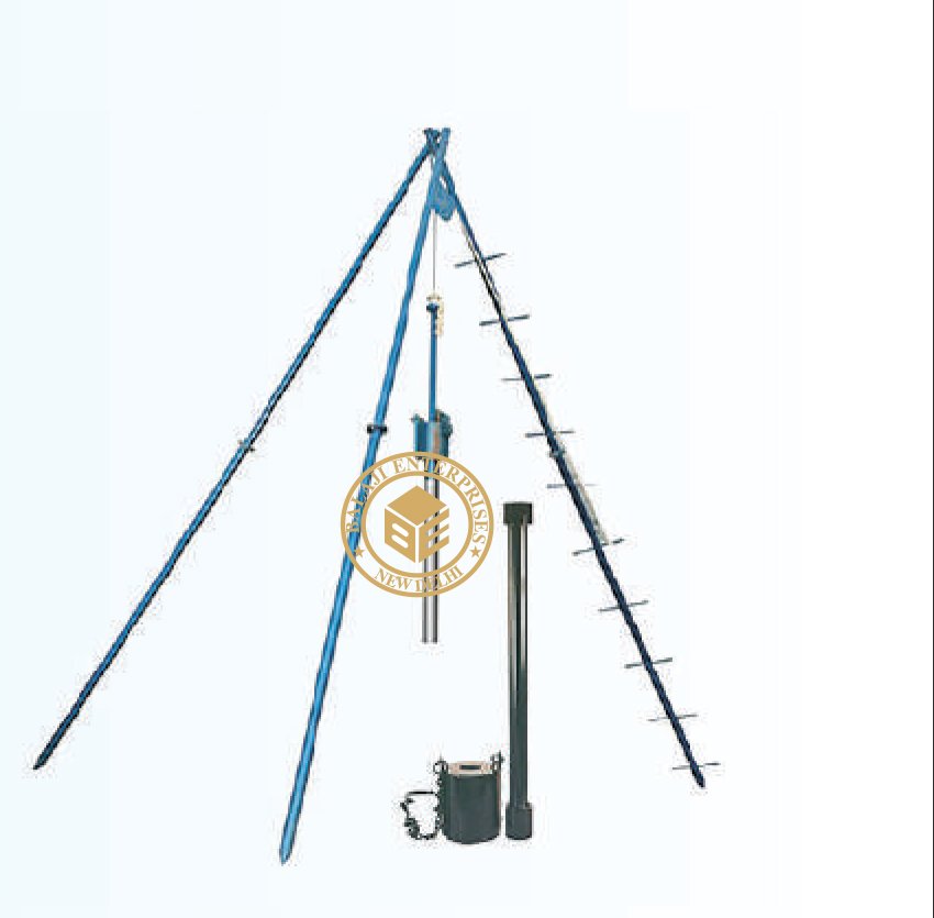
MODEL: -GT-076
IS 2131, IS 9640
This can be used in drilling operations to increase the footage & improve
jab safety consist of three metal pipe legs approximately 5 mtr. long
connected by a tie bolt each leg is made up of two parts for ease of
transportation complete with one pulley one leg has building ladder
Standard Penetration Test is a powerful tool for measuring the penetration
resistance of the ground and for relating it to the degree of compactness of
cohesionless soil and consistency of cohesive soil. The results can be used for
design of foundations. SPT is widely used for measuring the undisturbed
strength of the soil and for assessing its resistance to liquefaction due to
ground vibrations caused by earthquakes or other dynamic forces. The
Standard Penetration Resistance is measured as the number of blows ‘N’
required to drive a split spoon sampler to a depth of 300 mm using a 65 kg
weight falling freely through a height of 750 mm.
DROP HAMMER AND GUIDE PIPE
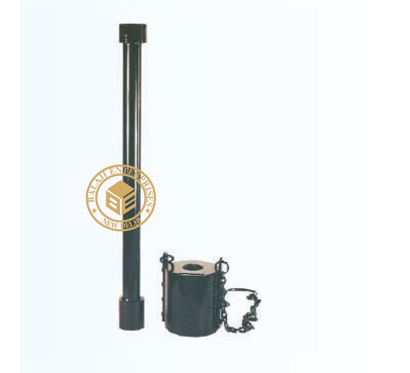
MODEL: -GT-078
For determining the resistance of different types of soil strata to dynamic
penetration of a 50 mm cone and thereby obtain an indication regarding
their relative strength or density or both. The method helps reconnaissance
survey of large area in a short time. Weight 65 Kg. Complete with two end
caps to give a free fall of 75cm the drop hammer
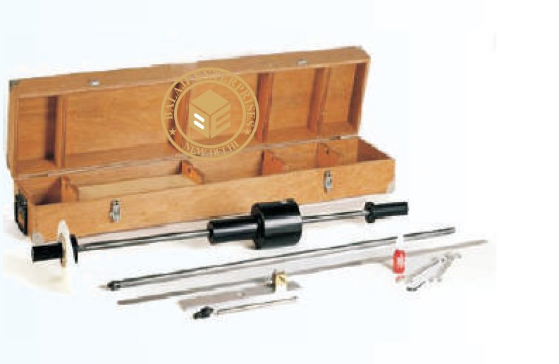
DYNAMIC CONE PENETRATION TEST
MODEL: -GT-079
The Dynamic Cone Penetrometer (DCP) is used for rapid in-situ measurement
of the structural properties of exsisting road pavement constructed with
unbound materials.The unit incorporates an 8 kg weight having a drop of 575
mm, fitted to the end of the shaft is a 20 mm diameter cone. With the standard
DCP measurements can be made down to a depth of approximately 850 mm.
Readings are usually taken after a set number of blows, changing the number
according to the strength of the layer being penetrated. For good granular
bases, readings every 5 – 10 blows are satisfactory, but for weaker sub-base
layers and subgrades, readings every 1 – 2 blows may be appropriate The DCP
requires three operators, one to hold the instrument in a vertical position, one
to raise the hammer and let it fall and one to record the results. A typical test
takes only a few minutes, providing a very efficient method of obtaining information which would otherwise require the
excavation of test pits. Where pavement layers have different strengths, boundaries can be identified and layer thickness
determined
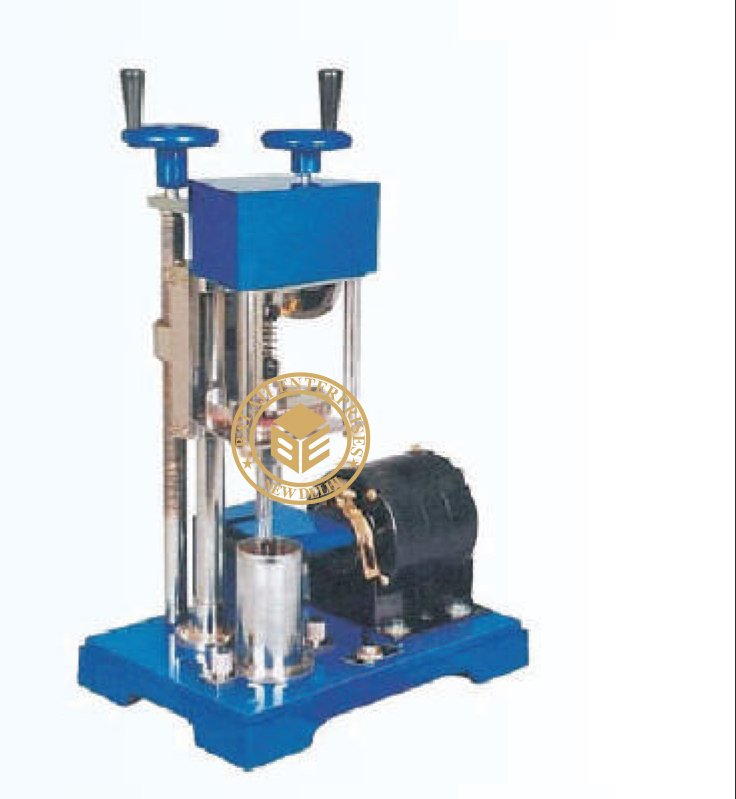
LABORATORY VANE SHEAR APPARATUS
MODEL: -GT-080
IS 2720 (XXX)-1968 BS 1377.
Consists of a torque head adjustable in height by means of a lead screw rotated
by a drive wheel to enable the vane to be lowered into the specimen. Rotation of
the vane is by means of a hand wheel which operates a worm gear arrangement
turning the upper end of a calibration torsion spring, vane dia, rod dia, vane size
& vane height are as per IS specifications. The vane shaft is attached through the
hollow upper shaft to a resettable pointer, which indicates the angle indicates the
angle of torque on a dial graduated in degree the dial reading multiplied by spring
factor gives the torque a container for soil sample is also supplied & a sampling
tube of 38mm. i.d. & 150mm long can also be used as container . Supplied with
set of four springs, one each of approx. 2 kgs/cm sq., 4kgs/cm sq., 6 kgs/cm sq.
& 8kgs/cm sq. complete as above in a wooden carrying case
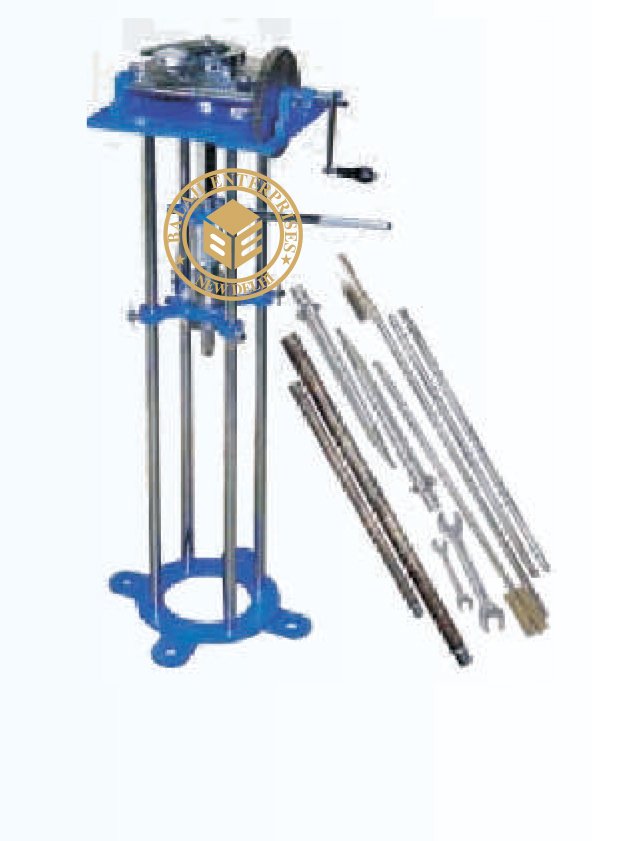
IN-SITU VANE SHEAR TEST APPARATUS
MODEL: -GT-082
IS 4434
This apparatus is designed for conducting in-situ Vane hear test from
the bottom of bore hole in saturated cohesive deposits, for determining
their in-place shearing resistance.The equipment consists of a torque
applicator assembly mounted on a base. A gear wheel, which is marked
in degrees, holds a torque ring and is geared to a crank. The torque ring
has a section cut from it and deforms as torque is applied and the resultant
deformation is indicated by a dial gauge. A pointer is provided for registering
the rotation of the vane. A detachable stand is provided to anchor the
instrument. An attachment to securely hold the string of rods is provided. A
calibration curve to convert the dial gauge readings to kg-cm of torque is also
supplied.
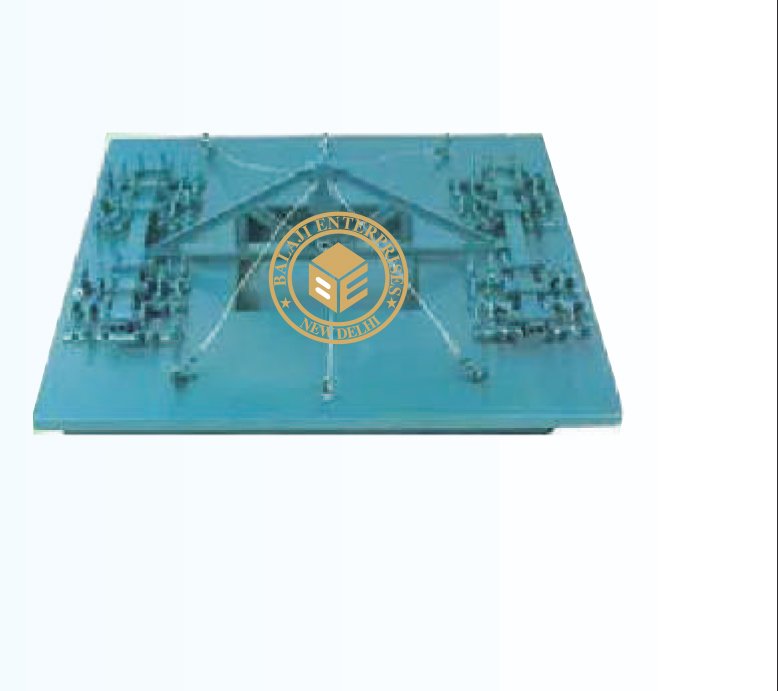
LOAD TRUSS 20 TON CAPACITY
MODEL: -GT-083
IS 1888 1962, ASTM D 1194, BS 13779
The truss is of welded 1- girder construction in two halves which can be bolted
together when required. The flower chord, the crosspieces for holding the truss
down and the truss down and the vertical thrust members are all of welded box
type construction with two channels enclosing and welded to an I girder. The
anchorages are of a design tried out and perfected at CBRI- Roorkee. They
consist of semi cylindrical pieces each held down by 3 feet long steel spikes driven
in through holes drilled in the semi cylinder. The spikes enter the ground at about
60 degree to the horizontal, four from each side spaced along the length of the
anchorage. The cross- pieces are moored to the anchorages by channel straps and
bolts. Eight such anchorages are supplied with the 20 ton truss.
SIEVE SHAKER
MODEL: -GT-084, 85, 86
Sieve Shaker
Sieve Shakers, hand operated or motorized, have been designed to provide a
standard sieving action for perfect and quick sieving of soil and other
engineering materials. The motorized unit save considerable time. Time
switch adjustable from 0-60 min., in time intervals of 5 min is provided as
standard along with the motorized sieve shakers.
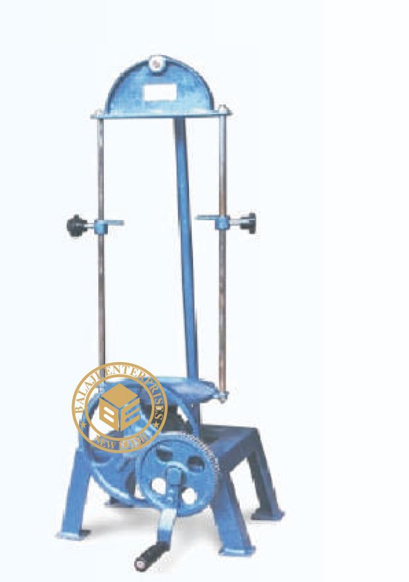
Sieve Shaker (Manually) 20cm (SL-GT-084)
This is a light, portable but sturdy sieve shaker suitable for bench mounting
the side to side movement to the carrier which can take upto 7 sieves of 200mm
dia is through a train of gears operated by a hand wheel. A heavy fly wheels
ensures smooth operation.
Sieve Shaker (Manually) 20cm, 30cm (SL-GT-085)
Same as above but carrier table & holder suitable to take 20 cm & 30cm (200mm & 300mm) dia sieves.
Sieve Shaker (Manually) 20cm & 30cm
Sieves Box Type (SL-GT-086)
Same as above but carrier table & holder suitable to take 20 cm & 30cm (200mm & 300mm) dia sieves.
'GYRATORY' SIEVE SHAKER
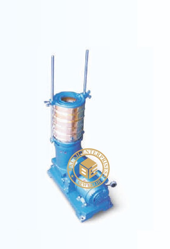
MODEL: -GT-087
Carries upto 7 sieves of 200mm or 300m, 450mm diameter. The shaker is
driven by a ¼ H.P. Motor through a reduction gear immersed in oil.
The sieve table does not rotate but is inclined from the vertical axis and
the direction on inclination charges progressively in clockwise direction. If
the stop pin below the table is removed, the shaker can have a rotary motion.
In addition to this gyratory motion of the table, there is an upward and
downward movement ensuring that each square cm of the sieve is utilized.
A pair of rods and a holder are supplied. The holder can be fixed on the top
of the upper most sieve, and thus the sieve set in firmly held. Suitable for
operation form 230 V, 50 Hz Single Phase A.C. Supply.
'ROTAP' SIEVE SHAKER
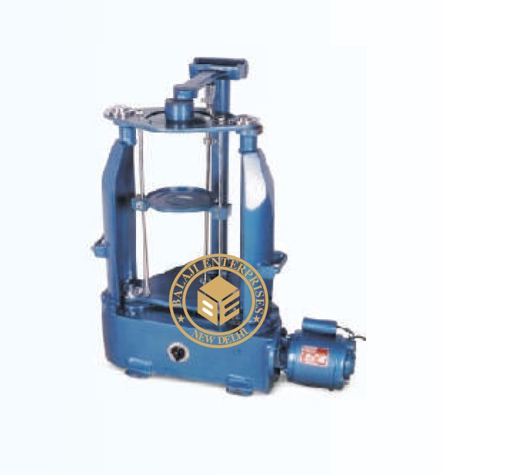
MODEL: -GT-088, 089
‘ROTAP’ Sieve Shaker (SL-GT-088)
To make process of sieving simpler and quicker, Rotap sieve shaker is useful ,
this produces circular shaking of the sieves. At the same time the sieves are
tapped. The mechanism for imparting circular action and topping is oil
immersed in a tank and in motorized. The shaker can accommodate upto 7
nos. Sieves of dia 200 or 300mm, 450mm Suitable operation of 230 V A.C.
Single Phase.
ACCESSORIES:
Time switch adjustable from 0-60 minutes in 5 minute intervals.
‘ROTAP’ Digital Sieve Shaker (SL-GT-089)
Same as above with Digital timer 0-99 x 1 minute.
WET SIEVE SHAKER, HAND OPERATED
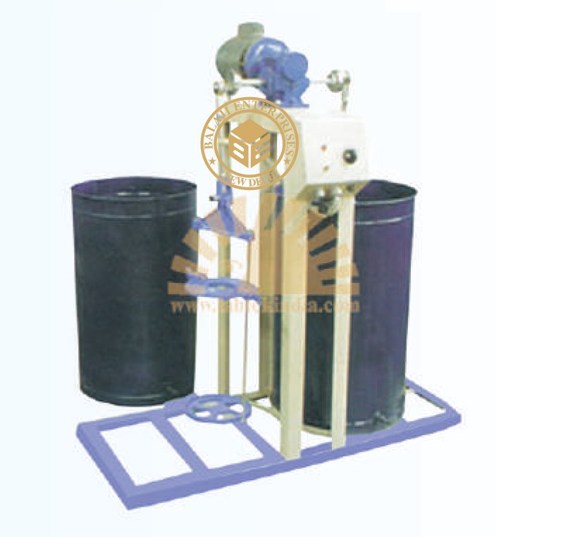
MODEL: -GT-088, 089
‘ROTAP’ Sieve Shaker (SL-GT-088)
To make process of sieving simpler and quicker, Rotap sieve shaker is useful ,
this produces circular shaking of the sieves. At the same time the sieves are
tapped. The mechanism for imparting circular action and topping is oil
immersed in a tank and in motorized. The shaker can accommodate upto 7
nos. Sieves of dia 200 or 300mm, 450mm Suitable operation of 230 V A.C.
Single Phase.
ACCESSORIES:
Time switch adjustable from 0-60 minutes in 5 minute intervals.
‘ROTAP’ Digital Sieve Shaker (SL-GT-089)
Same as above with Digital timer 0-99 x 1 minute.
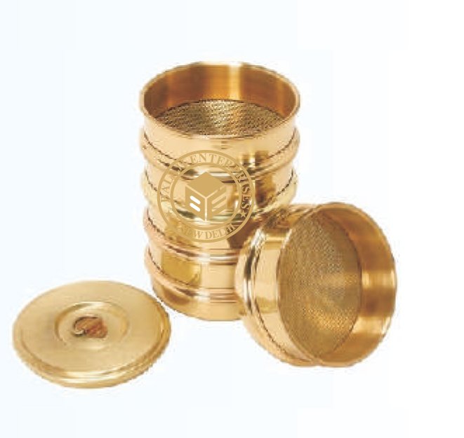
STANDARD TEST SIEVES 20CM DIAMETER, (SPUN BR ASS FRAME)
MODEL: -GT-093
IS :460 (Par t-I, II) 1978
Test Sieves is a common laboratory requirement. Sieves are used for sieving of
chemical powders, medical powders, aggregate, sand soil and cement etc.
These sieves are manufactured as per various standards like IS, BS, ASTM, DIN etc.
In Civil Engineering it is a common practice to use sieves for gradation and particle
size determination. Manufacturers brass frame and G.I. Frames Sieves of dia. 200mm,
300mm and 450mm. Normally brass sieves are manufactured in 200cm dia. and frame
is spun brass, The Sieve cloth used is standard SS or prosper bronze wire mush.
The G.I. Frames sieves manufactured normally n sizes 300mm dia. or 450mm dia.
have a steel perforated sheet having accurately punched square holes.
Size Available:
4.75mm, 3.35 mm, 2.80 mm, 2.36 mm, 3.00 mm, 1.70 mm, 1.40 mm, 1.18 mm, 1.00 mm, 212 µm, 180 µm, 150 µm,
125 µm, 106 µm, 90 µm, 75 µm, 850 µm, 710 µm, 600 µm, 500 µm, 425 µm,355 µm, 300 µm, 250 µm,
63 µm, 53 µm, 45 µm, 38 µm, 32 µm, 26 µm, 22 µm. Lid and Receiver for 200 mm dia sieves, made of brass.
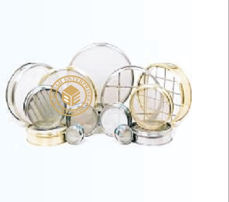
STANDARD TEST SIEVES 30 CM DIAMETER, (G.I. SHEET FRAME)
MODEL: -GT-095
IS :460 (Par t-I, II) 1978
Test Sieves is a common laboratory requirement. Sieves are used for sieving
of chemical powders, medical powders, aggregate, sand soil and cement etc.
These sieves are manufactured as per various standards like IS, BS, ASTM,
DIN etc. In Civil Engineering it is a common practice to use sieves for gradation
and particle size determination. Manufacturers brass frame and G.I. Frames
Sieves of dia. 200mm, 300mm and 450mm. Normally brass sieves are manufactured
in 200cm dia. and frame is spun brass, The Sieve cloth used is standard SS or
prosper bronze wire mush.
The G.I. Frames sieves manufactured normally n sizes 300mm dia. or 450mm dia.
have a steel perforated sheet having accurately punched square holes.
Size Available:
Sizes Available : 125mm, 106mm, 100mm, 90mm, 80mm, 75mm, 63mm, 53mm, 50mm, 45mm, 40mm, 37.5mm, 31.5mm,
26.5mm, 25mm, 22.4mm, 20mm, 19mm, 16mm,14mm, 13.2mm, 12.5mm, 11.2mm, 10mm, 9.5mm, 8mm, 6.7mm, 6.3mm,
5.6mm, 4.75mm, 4.0mm, 3.35mm, 2.36mm, 1.18mm, 1.00mm. Lid & receiver in G.I. Sheet frame for 300mm dia.
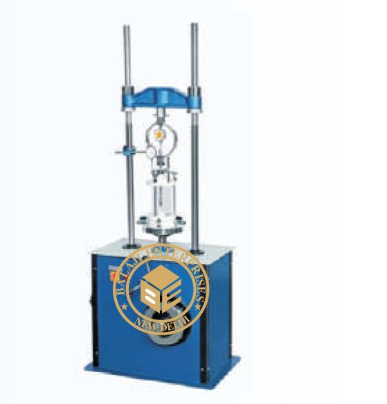
LOAD FRAME, MOTORIZED, 50 KN (1 SPEED)
MODEL: -GT-066
Triaxial Setup
Triaxial setup has different main components. These components are selected to
complete the setup. In the following pages specifications are given of each
components. Main component requirement for this test are:
I) Load Frame
ii) Triaxial Cell
iii) Lateral Pressure Assembly
iv) Measuring Unit
Load Frames
Load frame is essential equipment for carrying out Unconfined Compression, CBR and Triaxial Shear Tests. Since very
slow rates of strains are required for Triaxial Shear Tests LabTek load frame are made to suit the same. A suitable frame
can be selected from a wide range of LabTek series of Load frames depending upon the type of test and the size of sample.
Each load frame is provided with a standard proving ring adaptor having ½” BSF male threads to suit LabTek range.
Load Frame, Motorized, 50 kN (1 Speed)
It is a single speed load frame designed for 1.25 mm/min strain rate. It
can accommodate Triaxial cells up to 100mm diameter specimen.
Loading capacity is 50kN.Operates on 220V,50Hz supply
LOAD FRAME, HAND OPERATED, 50 KN
MODEL: -GT-065
Triaxial Setup
Triaxial setup has different main components. These components are selected to
complete the setup. In the following pages specifications are given of each
components. Main component requirement for this test are:
I) Load Frame
ii) Triaxial Cell
iii) Lateral Pressure Assembly
iv) Measuring Unit
Load Frames
Load frame is essential equipment for carrying out Unconfined Compression,
CBR and Triaxial Shear Tests. Since very slow rates of strains are required
for Triaxial Shear Tests LabTek load frame are made to suit the same.
A suitable frame can be selected from a wide range of LabTek series of Load f
rames depending upon the type of test and the size of sample. Each load frame is provided with a standard proving ring
adaptor having ½” BSF male threads to suit LabTek range.
Load Frame, Hand operated, 50 kN
The load frame is designed for a maximum load of 5000 kgf. It consists of a screw jack mounted in a reversible channel
frame, which can be used for loading from top to bottom and vice versa.
CBR APPARATUS (HAND OPERATED)
MODEL: -GT-056
California Bearing Ratio Test (CBR)
The C.B.R. Method is used for finding the relative bearing ratio and expansion
characteristics of soil of base, sub-base and sub-grade for the design of roads, p
avements and runways.
Test can be made on all types of soils including sand, gravel, crushed stone etc.
(Passing through 20mm IS sieve) C.B.R. test is used extensively for selection of
materials and control of sub-grades. The procedure of test is very simple. A 50mm
dia. penetration piston is forced in the test soil and loads required for the
penetration to penetrate different depths are recorded by means of a proving ring
fixed to the penetration piston assembly and a dial gauge. Both Laboratory C.B.R
and field C.B.R apparatus are available.
AS PER IS: 2270 (PART-XVI)
California Bearing Ratio Apparatus is made both for laboratory and field use.
CBR test is to evaluate the bearing capacity of soil for the flexible pavement design.
It is extensively used for the selection of mater ials and cont rol of subgrades. The
potent ial expansion/consolidation of the specimen is also measured before each test,
under known surcharge weights.
This apparatus comprises of :
A hand operated load frame 50kN capacity, A mould of 150 mm. I.D. x 175 mm. high with clamping lugs complete with e
xtension collar and perforated base plate made of gun metal. A cutting collar to fit mould body. A penetration piston
assembly of 50 mm. diameter and a bracket for the dial gauge. A perforated swell plate of 148 mm. diameter with an
adjustable stem and lock nut. A circular spacing disc of 148 mm. diameter x 47.7 mm. high complete with a removable
`T’ handle. A metal tripod for the dial gauge.
Surcharge weight :
annular _ 2.5 kg., 147 mm. diameter. Surcharge weight : slotted _ 2.5 kg., 147 mm. diameter.
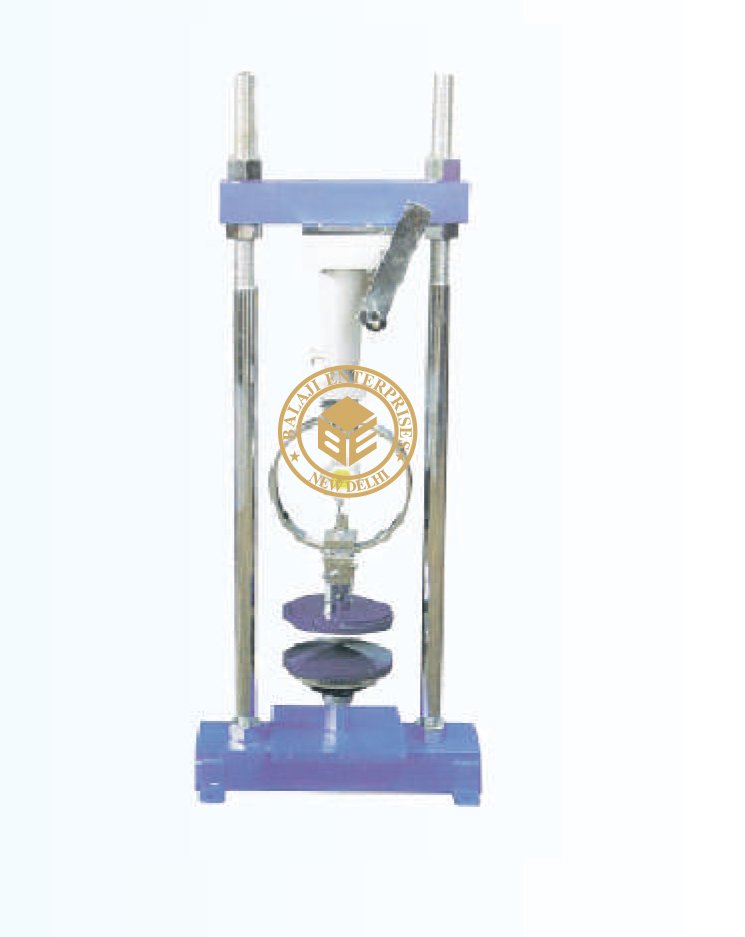
CBR TEST APPARATUS MOTORIZED
MODEL: -GT-057
IS : 9669, IS : 2720 (Part XVI)
It is used in large road construction projects has increased considerably in recent years.
This apparatus, mounted on a rolled steel joint cantilevered from the back of the truck
or fitted to the underside of a mobile frame, can be used to determine the bearing
capacity of soils quickly and efficiency. This method of testing in-situ, using piston
penetration, is useful for determining the load carrying capacity in the field, when the
in -place density and water contents are such that the degree of saturation is 80% or
greater. When the material is coarse grained and cohesionless so that it is not affected b
changes in the water content and when the material has been inplace. Similar to above
but supplied with bench mounting type 5000kgf. Capacity load frame motorized, in place
of load frame hand operated. The lead screw of the load frame has a single constant rate
of travel of 1.25mm/minute.
Dial Gauge 2 in. travel & 0.001 in division for CBR penetration measurement, having provision for increasing the dial
gaugeplunger length .Proving ring , 50 kN (5,000kgf) capacity x 0.5. kN/Div sensitivity/ readability, one with 25 kN
capacity x 0.04 kN / div sensitivity / readability and one with 10 kN capacity x 0.01 kN / div sensitivity / readability.
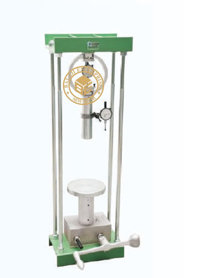
CONSOLIDATION APP. (SINGLE GANG)
MODEL: -GT-043
IS 2720 (Part XV), IS 12287, BS 1377, ASTM D 2435
Consolidation test is un-dimentional test considered extremely important in soil mechanics.
Sample taken from adjacent areas of a single site show differential settlement even when
tested using same techniques. Soil of similar strength may show varying consolidation.
Samples are very carefully prepared and vertical settlement of the specimen in saturated or
drained conditions carefully recorded when known load is applied.
SPECIFICATION:
The standard outfit comprises of the following items. Loading unit, maximum capacity
20kg/cm.sq. Having a loading yoke connected to a lever arm with a counter balancing
adjustment and having a lever ratio of 1:1 the whole assembly being mounted on a sturdy
teel frame stand. The loading unit is so designed that it can be used for consolidation cells of
different diameters as well as different dia floating ring type consolidation cells. Fixed ring
type Consolidometer (Odeometer) cell assembly for testing 60mm dia x 20mm thick specimen
comprising: Fixed ring for specimens 60mm dia x 20mm thick with guide ring. Top and bottom
porous stones for 60mm dia specimen. Perforated pressure pad, Channeled base with water inlet
and gasket Flanged water jacket, water reservoir with plastic tube and pinch cock. Set of weights
to give a pressure of 10kg/cm.sq. On 60mm dia specimen, comprising : 7 nos. 0.05 kg/cm .sq.,
5nos. 0.1 kg/sq.cm., 6nos. 0.5kg/sq. cm., and 5 nos. 1.0 kg/sq.cm. Supplied complete as above
but without dial gauge.
ACCESSORIES :
Dial gauge 0.002 mm x 10mm. Extension piece, 40 mm long, consolidation test forms pad of 50 for one dimensional
consolidation.
OPTIONAL EXTRAS :
Varying head stand pipe, 50cms. Long with mm. Scale. Fixed ring type of Consolidometer (Odeometer) cell assembly for
50mm. dia x 20mm thick specimens , complete with fixed ring guide ring. Pair of porous stones, perforated pressure pad,
channeled base, gasket and flanged water jacket. Set of weights to give a pressure of 10kg/sq.cm. on 50cm. dia specimen.
Fixed ring type of Consolidometer (Odeometer) cell assembly for 70mm dia x 20mm thick specimens, complete with
accessories as above. Set of weights to give a pressure of 10 kg/sq.cm. on 70mm dia specimens. Fixed ring type of
consolidometer (odeometer) cell assembly for 100mm dia x 25mm thick specimens, complete with accessories as above. Set
of weights to give a pressure of 10 kg/sq.cm. on 100mm. Dia specimens.

CONSTANT VOLUME MOULD
MODEL: -GT-036
Often in the laboratories it is required to quickly prepare remoulded soil specimen for
Triaxial and Unconfined tests. Constants volume moulds are used for this purpose, using
either dynamic or static compaction. The moulds are available in different sizes. For
specimen size 38 mm dia x 76 mm long comprises. Split mould 38 mm dia x 126 mm long.
End plugs 38 mm dia x 25 mm long pair. Split collar interchangeable. Ejecting plunger
38 mm dia x 126 mm long.
Accessories split mould 38 mm dia x 76 mm long and Split mould 38 mm dia x 86 mm long
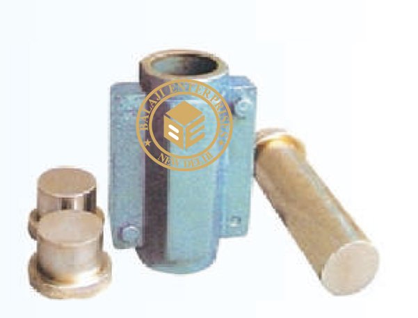
MOISTURE METER HYDROMETER
Model 3008
Display- range 4-60%: accuracy 0.1%
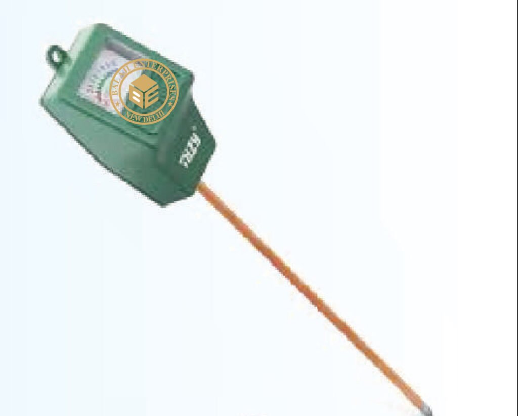
'ROTAP' SIEVE SHAKER
MODEL: -GT-088, 089
‘ROTAP’ Sieve Shaker (SL-GT-088)
To make process of sieving simpler and quicker, Rotap sieve shaker is useful ,
this produces circular shaking of the sieves. At the same time the sieves are tapped.
The mechanism for imparting circular action and topping is oil immersed in a tank
and in motorized. The shaker can accommodate upto 7 nos. Sieves of dia 200 or
300mm, 450mm Suitable operation of 230 V A.C. Single Phase.
ACCESSORIES:
Time switch adjustable from 0-60 minutes in 5 minute intervals.
‘ROTAP’ Digital Sieve Shaker (SL-GT-089)
Same as above with Digital timer 0-99 x 1 minute.
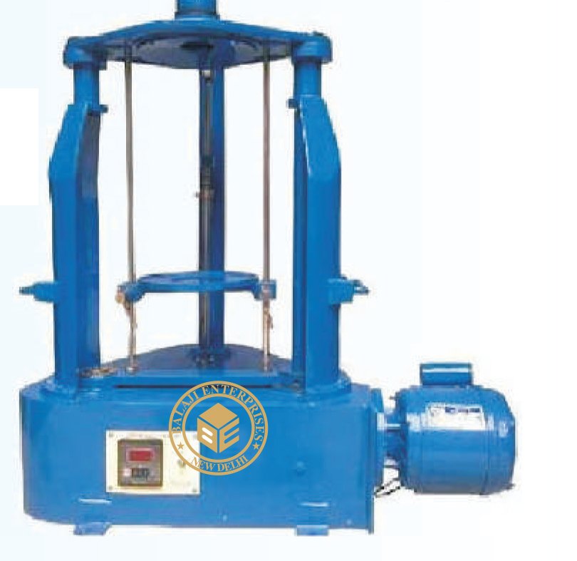
SC MODEL TORQUE COMPENSATED POWER PACK

Universal Testing Machine Capacity 50KN to 1000KN
Hydraulic Electronic Microprocessor Based Version Model : BE -009
Conforms to Grade A of BS:1610, Grade 1.0 of IS:1828
Ergonomically designed State of the Art Technology
Microprocessor based Digital Indicator Unit 2 Channels,
one for digital display of load in KN/KGF and the other
for Displacement in mm in bright, shadow-less display
Feather-touch push buttons for Tare, Peak Hold –Load,
Peak Hold – Displacement and Auto Calibration. Bright
Digital Display Resolution 20,000 Counts for load
Resolution for Displacement 0.01 mm .
Optional:
Resolution – 50,000 Counts for load and 0.01 mm or 0.001
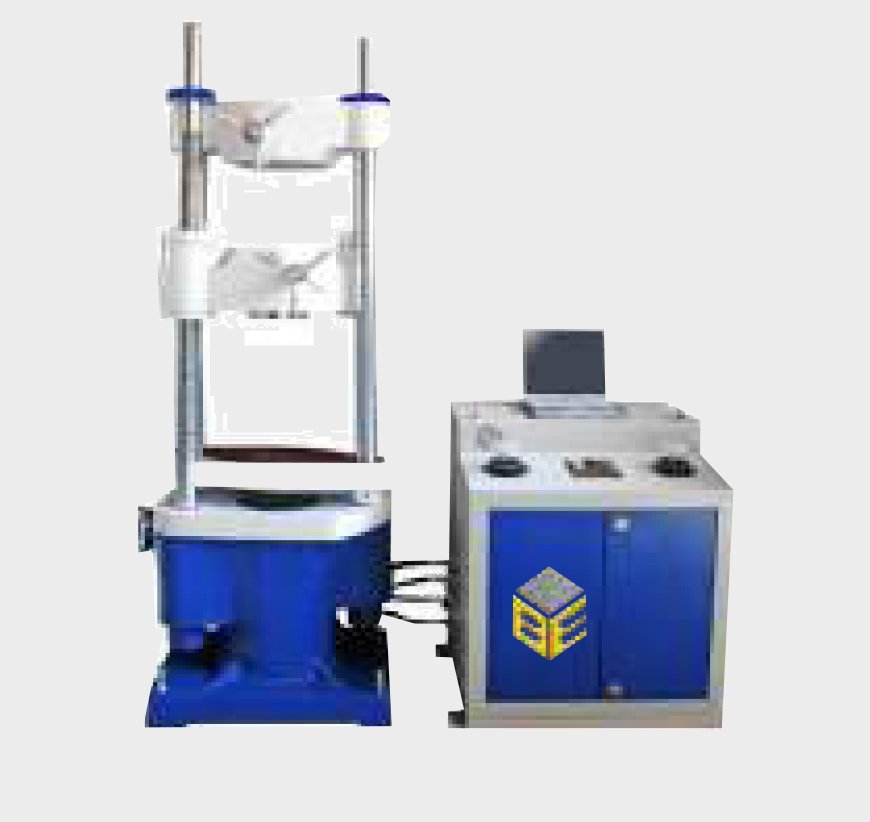
Hydraulic Computerized Version Model : BE-009A
APPLICATION SYSTEM:-
Peak load along with on line load
Maximum elongation with online elongation
Ultimate Tensile Strength
Graphical Display of load vs. time
Graphical Display of elongation vs. time
Graphic Display of load vs. elongation.
Graphic Display of stress vs. strain
Complete Statistical Analysis
Data Report
M
SAFETY FEATURES:
Machine stops after specimen failure Safety against Over travel of piston Safeguard against high temperature Surge Protection Auto Machine Diagnosis Safety against overload
PC CONFIGURATION:
Processor: i3/i5/latest available Processing Speed: 2.0 GHz or higher H.D. Drive: 200 GB RAM: 2 GB DVD RW: 8X Colour Monitor: 19″ LCD (Latest available at the prevalent time shall be supplied) ey Board: Multimedia Pri ter: Inkjeet Mouse Optal (Scroll type) UPS of at least 600 VA
SOFTWARE:
Preloaded with window XP / Vista / Window 7 based soft arre The sof are provided on CD ROM also Automatic s ving and providing database for carrying out statistal calculalation of multip est rst results are applicaplication is capable of providing functions li e Auto Return tto home position

Universal Testing Machine Capacity 1000KN Six Pillar Hydrulic Grip
APPLICATION SYSTEM:-
Supply and Installation of 1000 KN capacity Computerized Universal Testing Machine. The Equipment should have
following specifications: The loading accuracy as high +/-1 % of the indicating value. Equipment should be 6 pillar
structure with hydraulic jaw grip straight measurement at variable speed to cover a wide range of materials adjustable
by manual control valve. High reading accuracy rugged design of digital display. Simple control to facilitate ease of
operation. Robust load frame with extremely rigid construction.
Large effective clearance between columns enables testing o standard
specimen as well as structures. Motor driving threaded columns for
UP/ DOWN movement of lower cross head for quick change over of
specimen, grips and attunements. The Universal Testing machine
shold have resolution of 01.0 KN and Maximum clearance for tensile
test lies in the range of 50/650 mm and maximum clearance for
comparison test lies in 0 to 600mm range. The clearance between
columns in 650 mm and ram stroke is 250mm. The straining/ piston
speed at no load is 0-50 mm / minimum for tension test the clamping
jaws for round specimen are 8 to 16 mm, 13-26 mm, 26-40 mm
specification and clamping jaws for specimen thickness is in 0/30mm
range. The flat specimen width for tension test should be 70 mm and
for comparison test, the pillars for comparison plates diameter of circular
platen should be 220 mm. For the transfers test, the width and diameter
of rollers is 140 mm and 50 mm respectively. In the transfers test, the
maximum clearance between supports is 600mm and the radius of punch
ops comes in two different specifications that is in 16 mm and 22 mm.
The crosshead geared motor is of 0.37kw and power pack motor is of 2.20
kw. The machine should have microprocessor based electronic panel
precision load cell for load measurement, rotary and encoder for cross head
displacement/ extension indication, law card for PC inter-face, data entry for
specimen dimension, serial number, gauge length, unit selection for load
displacement. The result included load versus displacement curve, maximum
displacement, UTS, percentage, elongation, Young’s Modulus and proof stress.
The equipment should be provided with robust standalone and real time data
accusation system with universal ports, 18 BT resolutions, more than 10 analog
channels and 12 flexible digital channels, 8 by directional channels for state and
count input and state output. LCD display, interface all types of censors. The data
logger should have accuracy; 01 percentage of full scale, linearity 0.1 percent and
easy configurable windows based software. The equipment and software should be provided with relevant attachments to
conduct tensile est, comparison tests, transfers test for flat specimen, bend- re-bend, share and extensometers. The Extensometers
test screen incorporates the result of normal load versus displacement test as well as load versus extension online graphical
view simultaneously, a unique facility units own. The equipment to be provided with single conditioner, strain gauges and
temperature gauges. Electronic extensometers strain gauge type with 2.5mm extension and gauge length 25 and 50mm bend
test attachment 180, flexural test attachments, shear test attachments 6,8, 12, 16 and 20 dia shear test attachment 25,30,35 and
40mm dia Pair threaded holdings heads 6,8,10,12,16,18 and 20 mm, pair of threaded holding heads 6mm, 8mm,10mm,12mm,
16,18,20mm gripping devise for threaded and shouldered specimens, pair of splintering for shouldered specimen
6,8,10, 12,16,18,20mm per set, the approximately weight for the 1000KN universal testing machine is 3500 KG. The machine
should be calibrated in accordance with BS;1610 and IS standards. Universal Testing Machine comply with Grade A of BS 1610;
1964 and grade 1 of IS; 1828-1991. An accuracy of +/- 1 % is guaranteed from 20 percent of the load range selected to full load.
Below 20 percent of the selected range, the maximum permissible error is 0.2 % of the full load reading. The Universal Testing
Machine is suitable for operation on 440voltage, 50HZ, 3 Phase AC supply. The equipment to be supplied with Laptop and Laser
Printer with latest configuration to support the equipment software. The bidder has to submit detailed data sheet of the
equipment with all accessories as mentioned above and show the working of the equipment along with all attachments/
accessories to the department

APPLICATION SYSTEM:-
Perfection of diagramming functions Realize the testing diagram online display and reproduction. Zoom in or out the test diagram at any place with any rate. Auto suit the diagram according to display resolution Print “section diagram” function Coordinates point tracing to check the test results in each point. Test Report Creation est report Single material test report Batch material test report Customized test report Coordinates point test report
SUPPLIED COMPLETE WITH STANDARD ACCESSORIES FOR CONDUCTING TENSION, COMPRESSION SHEAR AND BEND/TRANSVERSE TEST ATTACHMENTS.
Servo Controlled Fully Automatic with touch screen Panel Universal Testing Machine Capacity 100Ton (1000KN) Model: BE-SCUTM-100
TENSILE TESTING
Used to test the tensile strength of steel rebar. The grippers of the machine are hand operated by 2 independent rack and pinions. Those grippers are designed to rmly hold the steel rebar and avoid any slipping that might happen during the test on the rebar. The lower mobile crosshead part of the machine is driven up/down by geared motor. It is used to adjust the distance between upper and lower grippers to suite the length of the steel rebar. Designed with different capacities (upon user’s request) such as: 400 kN (40 tons)/600 kN (60 tons)/1000 kN (100 tons) Capable of testing specimen with diameters ranging from 8 mm to 38 mm depending on the capacity. Provides easier and faster reporting with the printing facility for the results and graphs.
TENSILE TESTING TECHNICAL SPECIFICATIONS
1. Fully Automatic – PC Controlled
2. H and operated grippers by 2 independent rack and pinions
Lower mobile crosshead driven up/down by a separated motor adjusting the distance between upper and lower grips
3. A vailable models:
4. 4 00 kn (40 tons)
5. 6 00 kn (60 tons)
6. 1 000 kn (100 tons
Print of Load/Disp., Stress/Strain, Load/Time, Disp./Time Diagram and Test Results.
Application System
Peak load along with on line load.
Maximum elongation with online elongation.
Ultimate Tensile Strength
Graphical Display of load vs. time.
Graphical Display of elongation vs. time.
Graphical Display of load vs. elongation.
Graphical Display of stress vs. strain.
Complete Statistical Analysis.
Date Report Management
Safety Features:
Machine stops after specimen failure.
Safety against Over travel of piston.
Safeguard against high temperature.
Surge Protector.
Auto Machine Diagnosis.
Safety against overload
Computerized Servo Control Version
Stress Controlled kN/min
Strain Controlled mm/min
Air cooled Inter cooler.
On-Board characteristics linearizing.
Fully Computer Controlled.
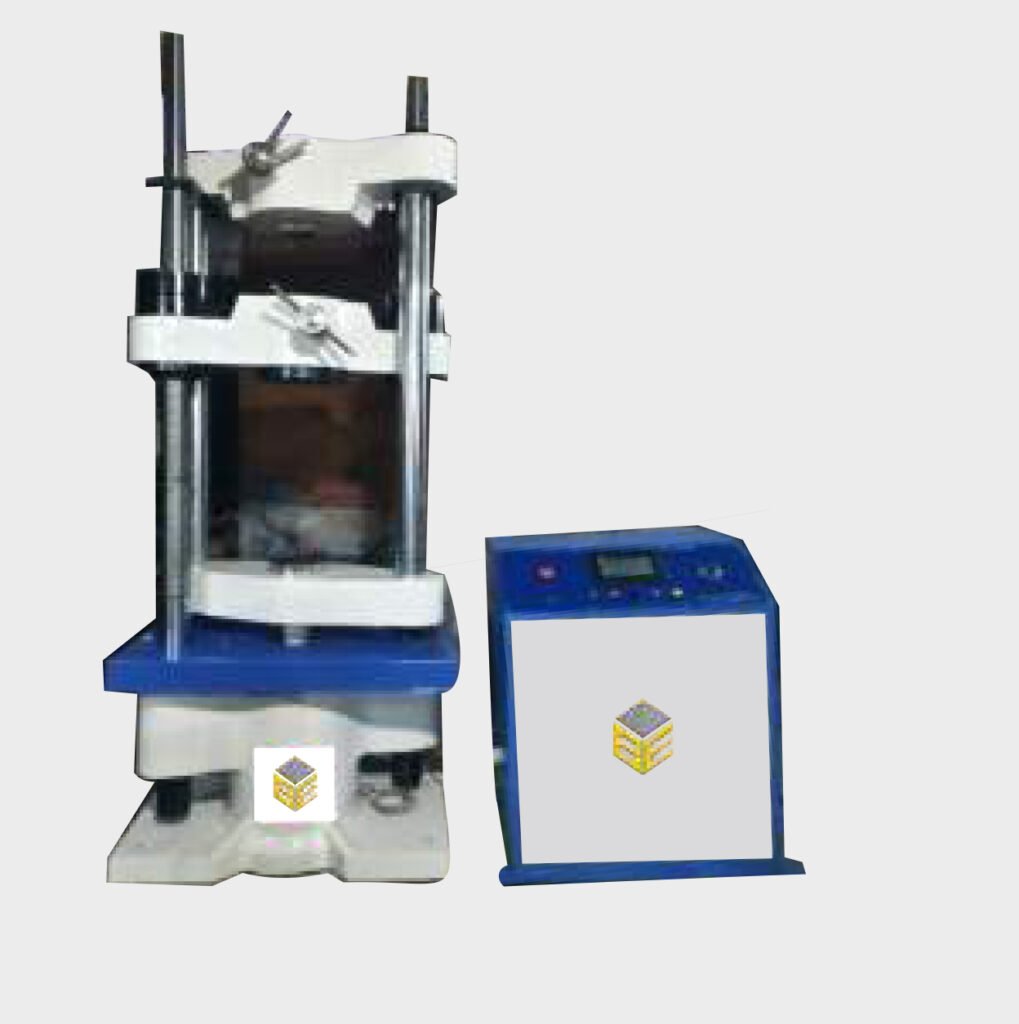
UTM Standard Accessories :-
For Tension Test :-
Clamping Jaws for Testing Round Specimens under Tension
Clamping Jaws for Testing Flat Specimens under Tension
For Compression Test :-
A pair of compression platens, duly hardened, ground and polished
with bottom platen provided with guide lines for placing the test
specimen co-axial with the hydraulic ram.
For Bending / Transverse Test :-
Table with Adjustable Rollers complete with Mandrel for conducting
Bending/Transverse Tests
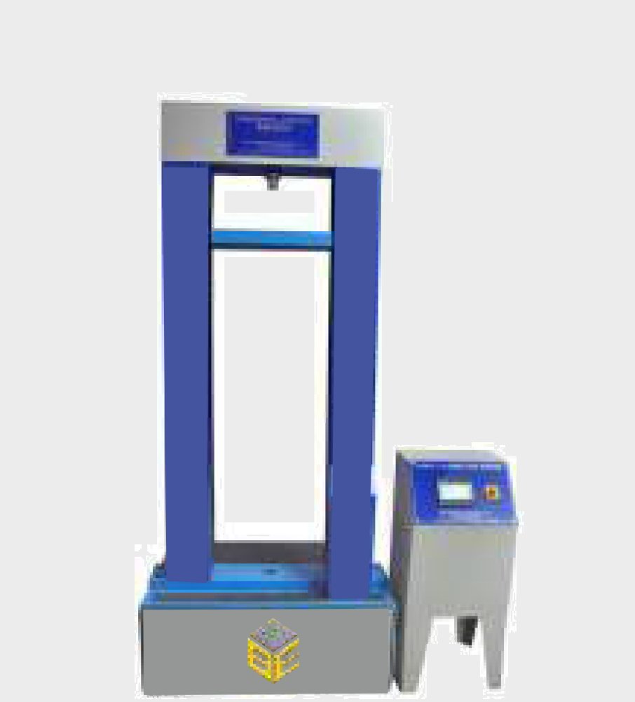
APPLICATION SYSTEM:-
Perfection of diagramming functions Realize the testing diagram online display and reproduction. Zoom in or out the test diagram at any place with any rate. Auto suit the diagram according to display resolution Print “section diagram” function Coordinates point tracing to check the test results in each point. Test Report Creation est report Single material test report Batch material test report Customized test report Coordinates point test report
SUPPLIED COMPLETE WITH STANDARD ACCESSORIES FOR CONDUCTING TENSION , COMPRESSION SHEAR AND BEND/ TRANSVERSE TEST ATTACHMENTS.
Servo Controlled Fully Automatic with touch screen Panel Universal Testing Machine Capacity 100Ton (1000KN) Model: BE-SCUTM-100
We are the leading manufacturer and supplier of Servo Control Computerized Universal Testing Machine made from high quality material.
Product Details:
DETAILED SPECIFICATION
Servo Based Compression testing Machine
Capacity 100kN
Accuracy Class 1 as per ISO 7500
Load Range 1%-100% FS
Load Accuracy Better than ±1% of reading
Load Resolution 1/500000 of capacity, stepless
Extension Measurement Range 0.02%-100%FS
Extension Measurement Accuracy Better than ±1% of reading
Extension Resolution 1/500000 of capacity
Displacement Measurement Accuracy Better than ±1% of reading
Displacement Resolution 0.025μm
Speed Accuracy Better than ±1% of setting speed
Max. Test Speed 500mm/min at no load
Min. Test Speed 0.001mm/min at no load
Return Speed 500mm/min at no load
Crosshead Speed Accuracy better than ± 1% of setting
Total Crosshead Travel (without grips) Minimum 1150mm (with standard columns) / 1300
mm (with Extended columns) without grips
Effective Test Width 600 mm
ESSENTIALLY WITH CLOSED- LOOP CONTROL
Compression Platen- Diameter- min.-200 mm
With 3 or 4 Point Bend Fixture – If with 3 point, then- bending nose R10, support roller R10, minimum span
340 mm – 1 set Software for Data Acquisition
The software should support the WINDOWS 7 and 8, as well as XP operating systems.
It should enable user to record and export test results in user defined templates, in WORD, EXCEL or
PDF etc. To be supplied with Integrated Computer DELL/LENOVA/HP/Apple make desktop/laptop,
factory integrated with the software and necessary hardware be supplied together with the machine.
If desktop, then, PC should have atleast-Intel i7 Dual core processor, 2 ethernet ports (1 on motherboard
and 1 on a PCI card), 16 GB RAM, 2 TB Hard disk, Graphic card, Expansion slots- four full height PCI
slots, One serial port and one parallel port, USB enhanced multimedia keyboard, wireless mouse, four
additional free USB ports, Window 8, Professional operating system (licensed), minimum 15 inch flat
panel LCD/LED monitor with at least 1980*1080 pixels, 220/240 V AC feed option If Laptop, then- should
have at least: Intel Core i7, RAM: 16GB ,Storage: 1TB HDD Display: 15.6- inch, 1980*1080 Pixels.
Automatic Compression Testing Machine 2000 KN Capacity with Touch Screen panel
MODEL NO.: BE-ACTM
Automatic Compression Testing Machine is capable of conducting compression tests on concrete specimens (Cubes and Cylinders) and allied products as per IS: 516/IS: 4031 Part 6: 1988/ASTM C 39 and conforms to requirement of IS: 14858-2000. These compression Testing Machine are state of the art machines based on the principle of CLOSE LOOP. The system can be loaded in load/stress control basis. The system accuracy is better than +/-1% of indicated value of load. A special type of 4 piece oil filled spherical seating is provided conforming to IS: 14858-2000. The system has an arrangement for automatic pacing system based on closed loop feedback principle, which is achieved by the combination of advance hydraulic and electronic system. Control signal from the electronic system is passed on to the control drive of the motor through the P.I.D. Controller which in turns control the flow to the hydraulic ram thereby keeping the pace rate within +/- 2% of the pre programmed value.
Salient Features:-
Load frame is steel welded fabricated structure. It is designed to withstand a few million times of full cycles of loading without any sign of distortion or fatigue. These frames are light in weight. The base carries a fine finished hydraulic ram and the lower platen. The top plate has the oil filled spherical seating to take care of any irregularity of the specimen surface or slight misplacement of the specimen from the central position. Front cover is provided as a protection to the operator while at the same time giving an unobstructive view of the specimen under test Proximity switch/ limit switch is provided as safe guard against over travel.
Load Frame
Conforming to Testing Procedures laid down in IS: 516/IS: 4031: Part 6: 1988/ASTM C39 for concrete specimen. Machine conforming to IS: 14858. Microprocessor based touch panel graphic display to control the machine operation and display of data. Programmable rate of loading (Pace rate) and other sample parameters. Real time display of load and peak load value with pace rate deviation bars. Inching/fast lift operation to adjust gap between sample and upper platen. Automatic release facility after sample failure Automatic strength calculation and display Peak stress calculation based on sample type, shape and dimensions Storing of results in user defined file with sample parameter and other details Transfer of result sheet to USB drive for printing and further analysis Safety limits for Over Load and Over Displacement ranges. The complete system consists of Load Frame, Hydraulic Pumping Unit, Microprocessor based touch panel display and control system & various height spacers to accommodate different size specimen.
Technical specifications
Max. Ram Travel : 50 mm Day light Clearance : 600 mm Horizontal Clearance : >300 mm Platen size : 256mm
Hydraulic Pumping System
Hydraulic pumping system, housed in an elegant console for low noise, consists of multi plunger pump driven by a suitable servo motor operated on 220 V, Single Phase, 50 Hz. This pump gives a continuous non pulsating oil flow to the ram of the loading frame. Pressure switch is provided for
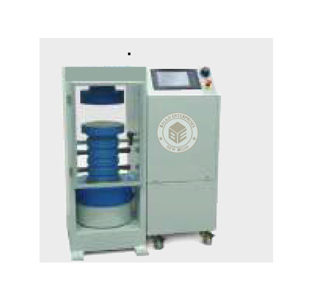
Compressive Strength Testing Equipment
Compressive Strength Testing Equipment to test cement, brick and
concrete is offered by us. The range we offer includes Manually
(Hand) Operated, Semi Automatic Compression Testing Equipment,
Electrically Cum Manually Operated equipment and more. These
strength testing equipment are extremely handy and are easy to use
for testing cement, concrete and mortar cubes. We lay utmost
importance on equipment design and construct with emphasis on
ease of operation. As present day buyers expect more power, speed
and highest level of accuracy in material testing system, we continue
to offer research based Compressive Strength Testing Equipment of
international standard, at affordable prices.
Compression Testing Machine (Manually)
(2 Pillar Model): Compression Testing Equipment Manually (Hand)
Operated fitted with single load gauge. The loads are measured on
Bourdon tube type load gauges which are calibrated against
certified proving rings. The load gauges are fitted with a maximum
BE-CC-001 load pointer.
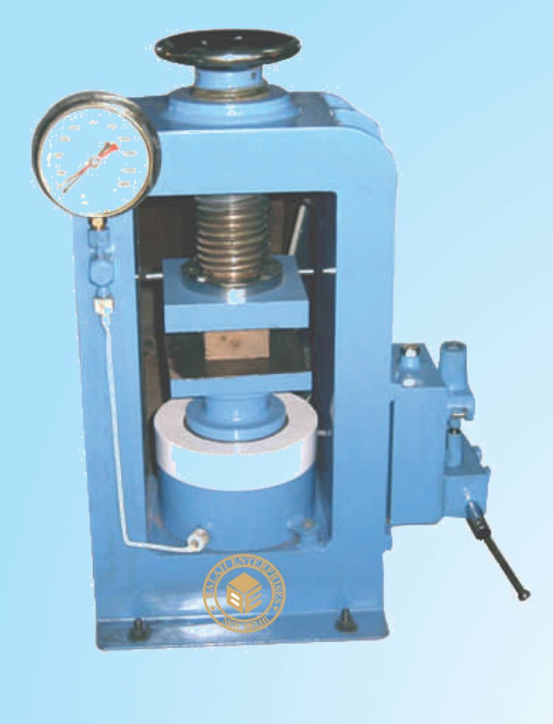
Cube Mould
For concrete compressive strength testing we offer highly
sophisticated testing machines duly made by our engineers and
technicians keeping in mind the overall usages. Our concrete
compressive strength testing machines includes concrete strength
testing moulds like Cube Moulds, Beam Moulds, Cylindrical Moulds
along with Flexural Strength Testing Machine that are equipped with
the latest designs and operating principle.
Four standard sizes of cube moulds are offered and supplied
complete with base plate.
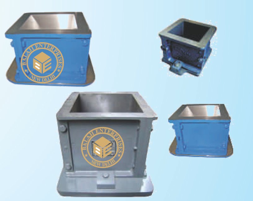
Semi Automatic Compression Testing Machine (Electrically Cum Manually Operated (2 Pillar Model)
Compression Testing Equipment Electrically cum Manually (Hand)
Operated. The loads are measured on Bourdon tube type load
gauges which are calibrated against certified proving rings. The load
gauges are fitted with a maximum load pointer. In the Electrically
Operated Pumping Units, load gauges are fitted with micro switches
to switch-off the motor when the load approaches the maximum
capacity of the gauge, avoiding any over loading. Relays are
incorporated so that the motor does not restart on its own after a
power breakdown. The electrically operated pumping units are
provided with a control knob to adjust the pace rate which can be
effectively controlled by an experienced operator during the course
of testing, by observing the progress of the load gauge reading. The
electrically operated pumping units are also fitted with hand
operated pump.
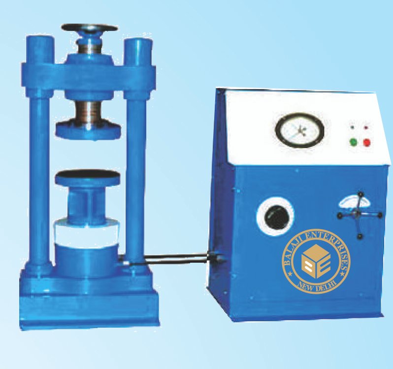
Digital Compression Testing Machines Semi Automatic Digital Compression Testing Machine ( Electrically Operated )
(2 Pillar Model):The Digital Compression Testing Machine has been
designed to meet the need for a simple, economic and reliable
means to test concrete for its compressive strength. The Digital
Indicator incorporates a 4-Digits display calibrated in Kilo Newton
(KN) and preset to maximum load capacity fitted with micro switches
to switch-off the motor when the load approaches the maximum
capacity of the gauge, avoiding any over loading. Relays are
incorporated so that the motor does not restart on its own after a
power breakdown. The electrically operated pumping units are
provided with a control knob to adjust the pace rate which can be
effectively controlled by an experienced operator during the course
of testing, by observing the progress of the Digital Indicator
readings.
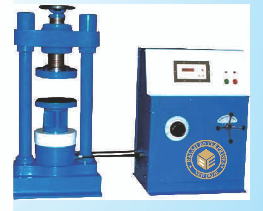
Fully Automatic with Touch Screen Panel
computerized compression testing machine.compression testing machine
The Digital Compression Testing Machine has been designed to
meet the need for a simple, economic and reliable means to test
concrete for its compressive strength. The Digital Indicator
incorporates a 4-Digits display calibrated in Kilo Newton (KN) and
preset to maximum load capacity fitted with micro switches to
switch-off the motor when the load approaches the maximum
capacity of the gauge, avoiding any over loading. Relays are
incorporated so that the motor does not restart on its own after a
power breakdown. The electrically operated pumping units are
provided with a control knob to adjust the pace rate which can be
effectively controlled by an experienced operator during the course
of testing, by observing the progress of the Digital Indicator
readings.
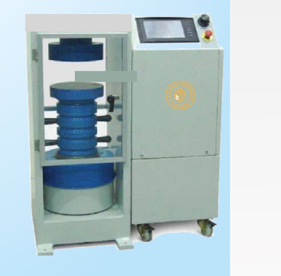
Semi Automatic Digital Compression Testing Machine ( Electrically cum Manually Operated - Fabricated Model with Load Gauge )
Compression Testing Machine has been designed to meet
the need for a simple, economic and reliable means to
test concrete for its compressive strength. The Load is
displayed simultaneously on the Digital Load Indicator
which incorporates a 4-Digits display calibrated in Kilo
Newton (KN), preset to maximum load capacity and also
on Bourdon tube type Load Gauge with a maximum load
pointer. The Indicators are fitted with micro switches to
switch-off the motor when the load approaches the
maximum capacity of the gauge, avoiding any over
loading. Relays are incorporated so that the motor does
not restart on its own after a power breakdown. The
electrically operated pumping units are provided with a
control knob to adjust the pace rate which can be
effectively controlled by an experienced operator during
the course of testing, by observing the progress of the
Digital Indicator readings or the Load Gauge readings.
The electrically operated pumping units are also fitted
with hand operated pump.
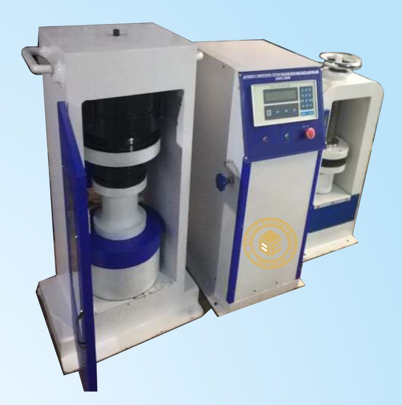
Flexural Strength Testing Machine
The Flexure Strength Testing Machines are designed to provide
maximum rigidity throughout their working range. The load is
applied by the upward movement of a hydraulic ram. The jack can be
raised or lowered for testing different size beams. The load is
indicated on a calibrated Bourdon tube type Pressure Gauge of
range: 0-100kN x 0.5kN (0-10,000 kgf x 50 Kgf). The load gauge is
calibrated against NPL/ NCCBM certified proving ring.
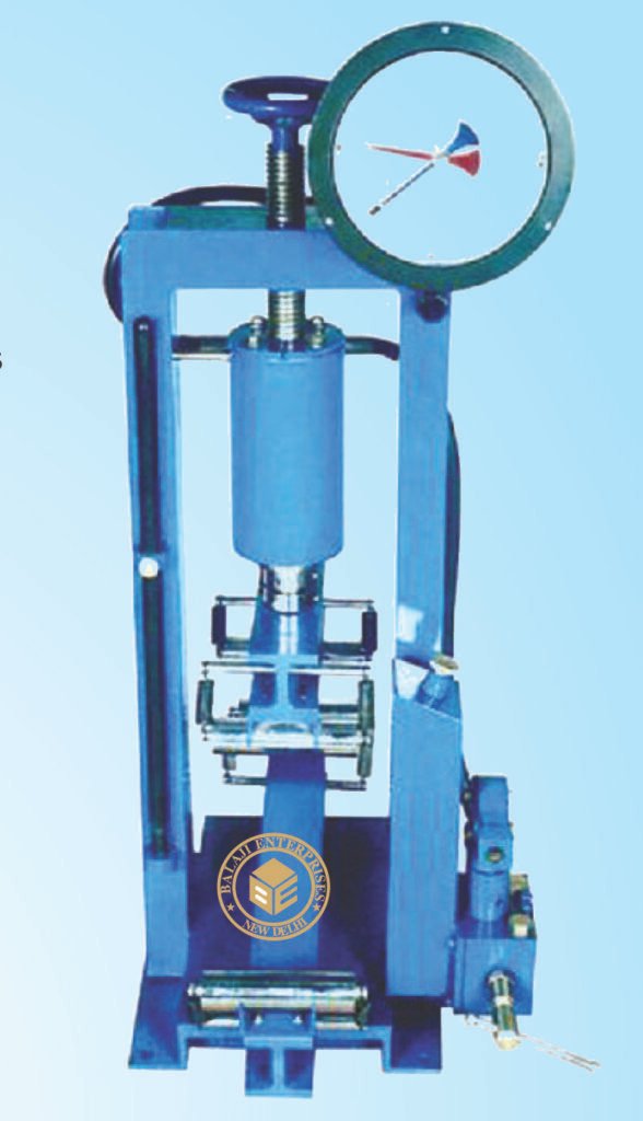
Beam Mould
Two standard sizes of Beam Moulds are offered for casting concrete
specimens for flexural strength testing. These beam moulds are
made of cast iron and are supplied complete with a base plate.
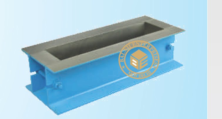
Cylindrical Mould
Moulds for testing concrete cylinders for Compressive Strength
Testing are offered in two different sizes. These cylindrical moulds are
made of Cast Iron and split into two parts longitudinally. These are
supplied complete with a base plate and top plate
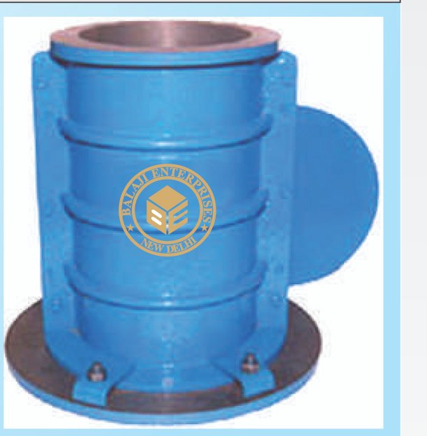
Proving Rings
Specification: The Proving Rings ar e made of special steel, carefully
forged to provide high and stable accuracy , dependability and
repeatability. The dial gauge and anvil are mounted on U-brackets
clamped to the ring body by set screws. The indicator has a sensitivity
of 0.002mm/ div and the deflection is directly proportional to the
applied load. The rings are supplied complete with dial gauge and
Works Calibration Chart, individually packed in polished wooden
boxes. NPL (India) / NCCBM Calibration Certificates can also be
arranged for any proving ring at an additional cost. Separate Pair of
Loading Pads are provided to suit each proving ring.
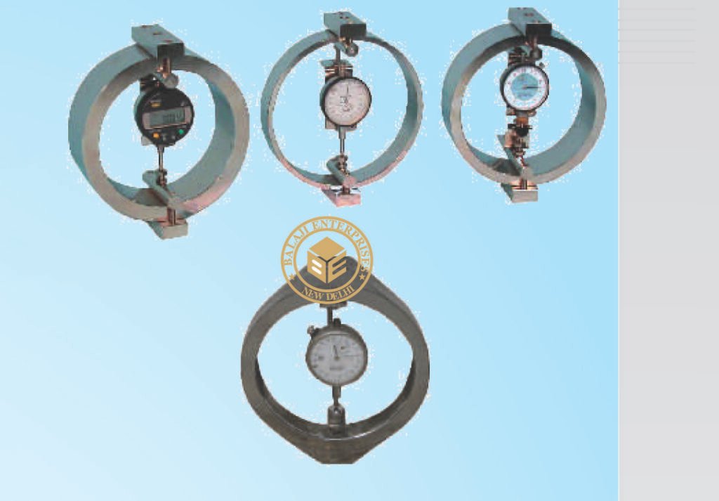
Cement Sampler
IS 7535 1986 ASTM C183 AASHTO T127
This is a brass tube approximately 53 cm long and 2.8 cm I.D. with a
wooden handle. Total length approximately 73cm. The tube has the
sharp angular edge which conveniently pierces cement bags. An air
hole of approximately 3mm dia is drilled on the tube near handle.
Total sample collected at one time is 300 cm approximately
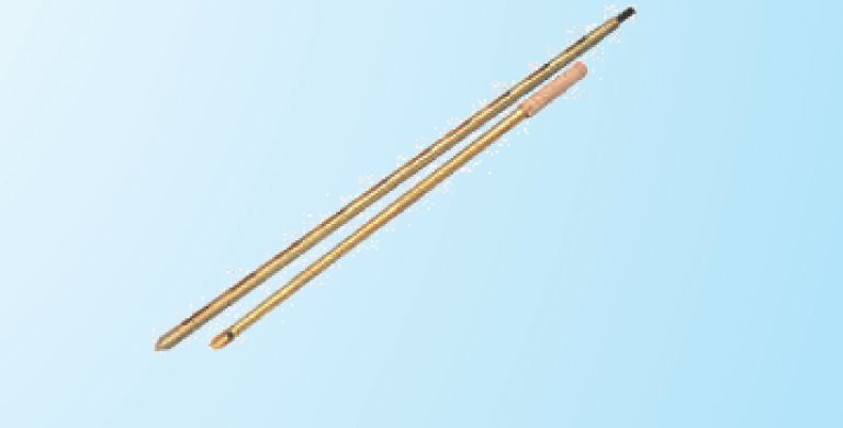
Blaine's Air Permeability Apparatus
IS 4031, 5516, 1727 & 4828, ASTM C-204 BS 4359-2
The apparatus is used for determining the fineness of cement in
terms of specific surface expressed as total surface area in square
centimeters per gram of cement. This is a variable flow type are
permeability.
Specification: The apparatus consists one each of permeability cell
12.5mm I.D. manometer ‘U’ type mounted on stand with a built in
stop cock, perforated disc, plunger rubber stopper, rubber tube
30cm long. Packet of 12 filter paper disc and a bottle of 100ml
dibutylphthalate liquid.
Vicat Needle Apparatus
IS 4031, 2645, 2542 ( PAR-1), 1727, 5513 & 712 BS 12, 146, 915, T
1370, 4027, 4246, 4248 AASHTO T 129, E 131.
This instrument is used for determining the normal consistency and
setting times of cement and ‘A’ class limes.
Specification: The apparatus consists of a metallic frame bearing a
freely movable and with a cap at top, one vicat mould and glass base
plate and one set of needles one each initial needle, final needle and
consistency plunger.
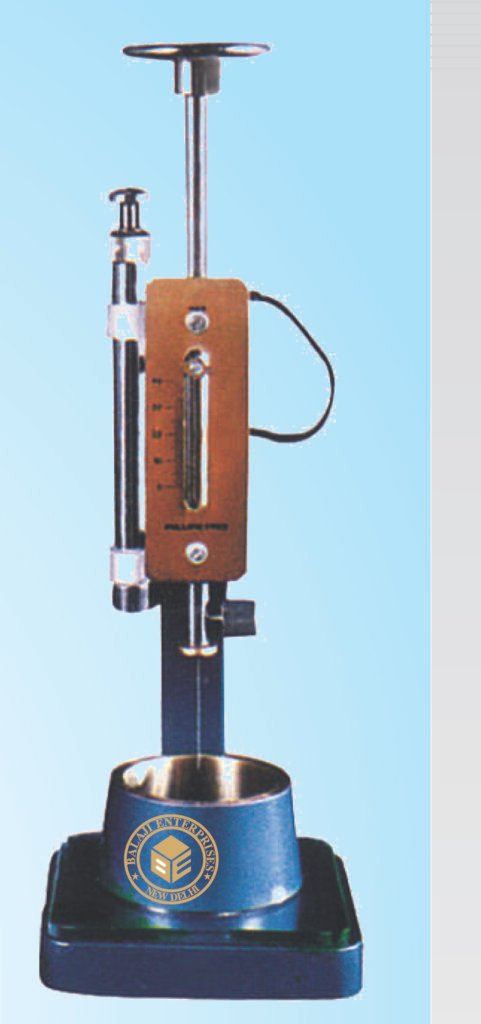
Vicat Needle App. with Dashpot
IS 4031, 2645, 2542 ( PAR-1), 1727, 5513 & 712 BS 12, 146, 915, T
1370, 4027, 4246, 4248 AASHTO T 129, E 131.
Specification: Same as Vicat Needle Apparatus but in addition is
fitted with a dashpot which facilities gentle lowering of the needles.
Accessories: Mild steel base plate 5 inches x 5 inches.
Fulcrum mould, brass, 70mm i.d. base dia. x 60mm i.d. top dia., 40
mm height.
Note:1) Normally set of needles and mould which meet is
requirements as per I.S. 5513 are supplied. While ordering please
specify the specification code of the instrument required.
2) Vicat needle apparatus for determining consistency of hydraulic
cement. Gypsum plaster, lime etc. As per ASTM C 187-58 C 472-62
C 110-58, IS 2542 (Part-1) can also be supplied.
Gillmore Needle Apparatus
ASTM C 266
This instrument is used for determining the time setting of hydraulic
cement.
Specification: A base with a Vertical shaft and Two horizontal arms.
The lower arms is adjustable for height. 1 no. Initial needle 1/12-inch
dia. ¼ lb. Wt. 1 no. Final needle 1/24 inch dia. ¼ lb. Wt. 1 no. Glass
base plate. Complete as above.
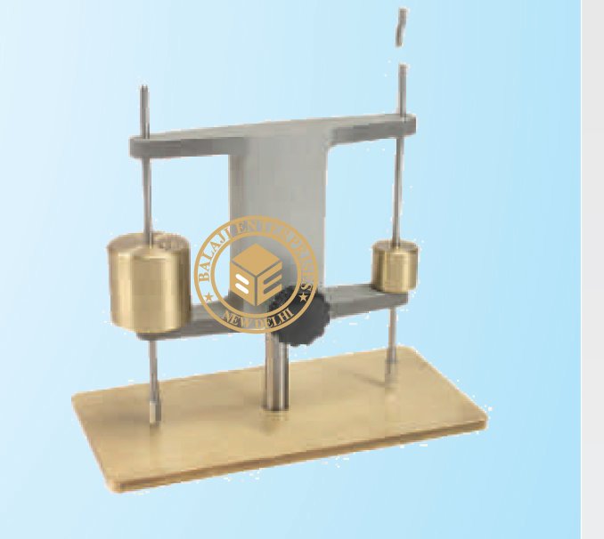
Kelley Ball Penetration Apparatus
ASTM C-360
The apparatus is used to determine the work ability of Portland
cement & concrete. The Kelly ball test is considered to be simple and
much faster than the slump test. Twice the Kelly ball reading
approximately equals the slump. It consists of a cylinder with a ball
shaped bottom and handle, together weighing 15 kg. A strip frame,
guides the handle and serves as a reference for measuring the depth
of penetration. The handle is graduated in mm. Penetration can be
recorded to the nearest 0.5mm.
Kelley Ball Penetration Apparatus
Heavy-duty, cast-aluminum design with quick release latches.
Provides convenience for the operator and protection to Kelly ball
when transporting to and from the job site.
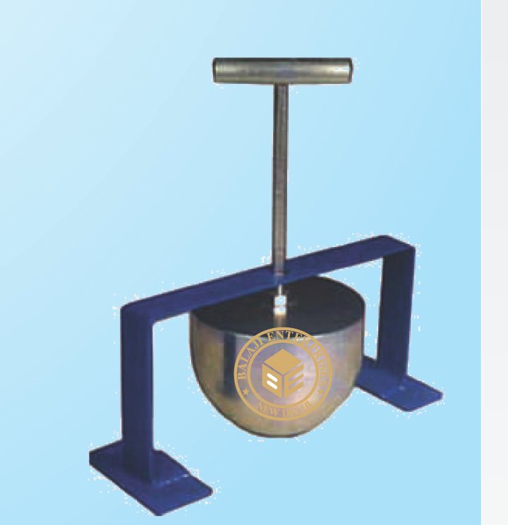
Flow Table
IS : 6932 ( PART VIII) ASTM C 230,BS 4551:1
This is used for determining the work ability of building limes.
Specification: The flow table consists of a 30 cm dia. polish steel
plate with 3 engraved annular circles 7, 11 and 19cm dia. The table
top is arranged for a free fall of 12.5mm by a cam action. Supplied
complete with one brass conical mould, 65mm i.d. at base and
40mm i.d. at top, height of the mould 90mm.
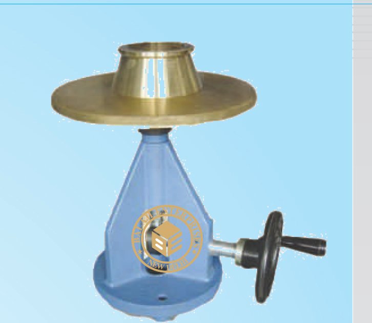
Flow Table
IS 1199-1959, ASTM C-124, AASHTO-T-120.
It is used for determining the flow of cement concrete.
Specification: Consists of a steel table top 76.2cm (30 inch. Dia)
Finely machined. The integral cast ribs are designed for support and
strength. The stand is fabricated out of cast iron and is of study
construction. Holes for mounting in foundations are drilled in the
base plate. The ground and hardened steel cam is designed to fit and
drop the table by 12.5mm. The hand wheel makes it simple to
operate the table. Supplied with one conical mould with two
handles, 12cm height, having17cm. Inside Dia. at the top and 25cm
inner dia. at the base. Complete with a tamping rod 16mm dia x
600mm long one end rounded.
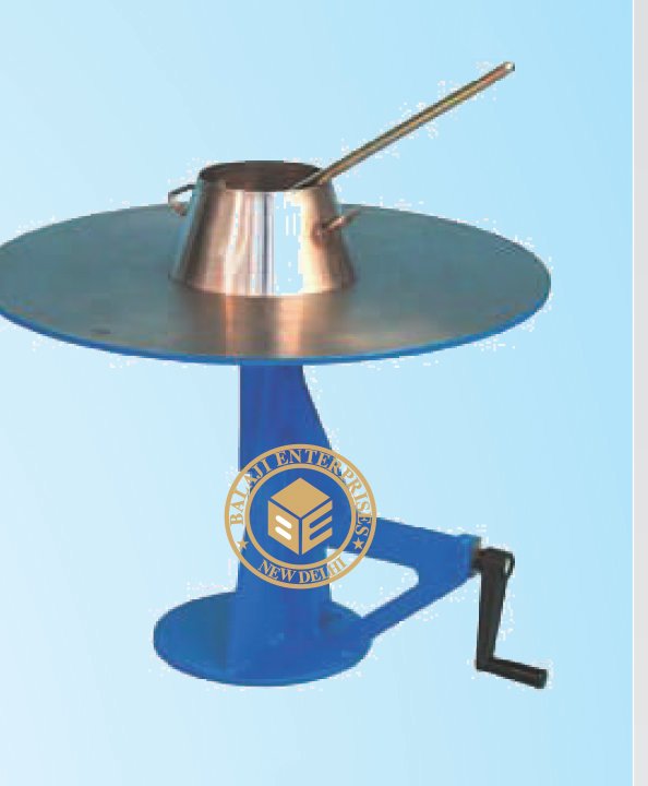
Flow Table (Motorized)
IS 1199, ASTM C-124, AASHTO-T -120
Same as above but electrically operated to raise and drop the table
top, approx. 15 times in 15 seconds, Suitable for operation on 230
Volts, 50 cycles, A.C. supply.
Flow Table: IS 5512 & BS 4551-1
This used for measuring the consistency of pozzolana and also
cement mortar and hydrated lime.
Specification : It consists of a machined brass table top 250+/-
2.5mm dia. Mounted on a rigid stand. The table top is reinforced
with equally disposed ribs and allowed to conical brass mould
100mm i.d. top dia. and 50mm high.
Accessories : Mild steel plate 25mm thick and 25cm square for
fixing to the underside of the base. Same as ZI 1008 but electrically
operated to raise and drop the table top, approx. 15 times in 15
seconds, Suitable for operation on 230 Volts, 50 cycles, A.C. supply.
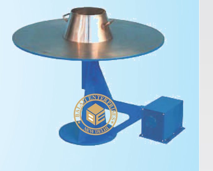
Flow Table (Motorized)
IS 5512 & BS 4551-1
Same as above but electrically operated. Fitted with a motor,
connected to the cam shaft through a reduction gear to give
approximately 100 R.P .M. Suitable for operation in Single Phase 230
V A.C. 50 Cycles, Supply
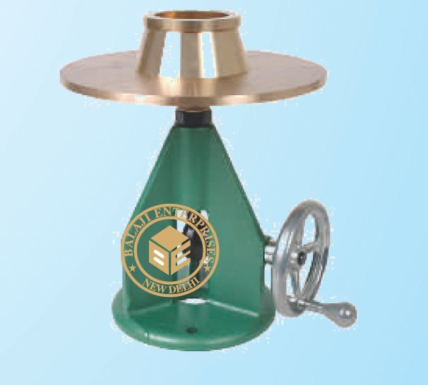
Ve Bee Consistometer
IS 1199 & BS EN 12350.
The instrument is used for work ability as well as consistency of fresh
concrete. A slump Cone and a graduated rod supplied with the
instrument helps the operator to find out slump values and vibration
table with container and acrylic disc is used to find out work ability of
concrete expressed in Vee Bee degrees, which is defined as the time
in seconds to complete required vibrating at which the fresh
concrete flows out sufficiently to come in contract of the entire face
of acrylic disc.
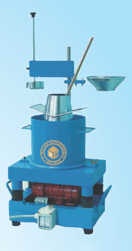
Slump Test Apparatus
As Per IS 1199, IS 7320
Specification : The slump cone in these slump test apparatus is filled
with freshly mixed concrete and tamped with a tamping rod in three
or four layers. The top of the concrete is leveled off with the top of
the slump cone, the cone is lifted vertically up and the slump of the
sample is immediately measured. The complete slump test
apparatus set comprises of a Steel Octagon Base Plate (8 faces) with
carrying handle, Graduated Tamping Rod 16mm dia. x 600mm long
with one bullet end, slump cone having base 200mm, height
300mm fitted with handle.
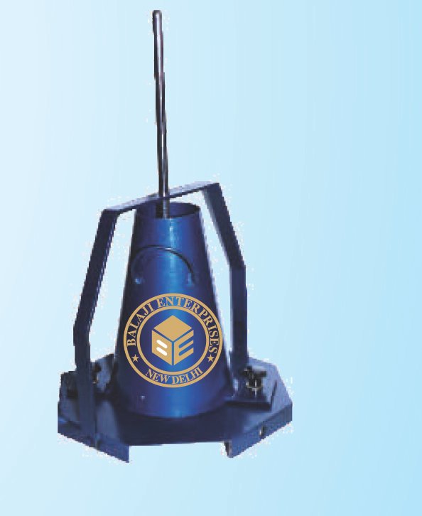
Compaction Factor Apparatus
IS 1199, 5515. & BS 1881-103
The apparatus is used for determining the work ability of fresh
concrete, provided the maximum size of the aggregate does not
exceed 38mm. The test is particularly useful for concrete mixes of
very low work ability where true slump values are not reliable.
Specifications: It consists of two rigid conical hoppers and a
cylinder mounted on a rigid metal frame. The lower openings of the
hoppers are fitted with hinged trapdoors having quich release
catches. A circular metal plate is provided to cover the top of the
cylinder. Supplied complete with one plasterer’s trowel and one
tamping rod, 16mm diax600 mm long, one end rounded.
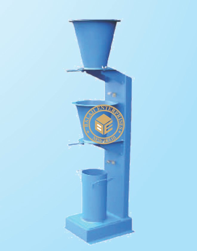
Lab. Concrete Mixer (Manually)
Our hand operated concrete mixers are easy to operate. Durable in
quality and requiring low maintenance cost, our machines are widely
used in construction of buildings, houses, road and other
construction purposes. Highly resistant to corrosion and better
performing, these machines have been widely demanded by our
clients across the globe.
Lab. Concrete Mixer (Motorized)
Specification: The Laboratory Concrete Mixer is used for preparing
Mix Design of Concrete. It consists of a steel vessel of 55/ 110 Litres
capacity, mounted on a frame. The vessel is rotated at 20-22 RPM
with the help of a motor and a pulley arrangement. The vessel of
laboratory concrete mixer can be titled to any angle by a hand wheel
and counter weight. This facilitates mixing and discharge. Blades are
provided inside the vessel to mix the material thoroughly. The large
pulley wheel facilitates manual rotation of the drum during power
failure. The drum, pulley wheel, and motor, etc, are mounted on a
steel frame in these laboratory concrete mixer. The concrete mixer is
fitted with ½ HP motor. Suitable for Operation on 220V, Single
Phase, 50Hz, AC Supply
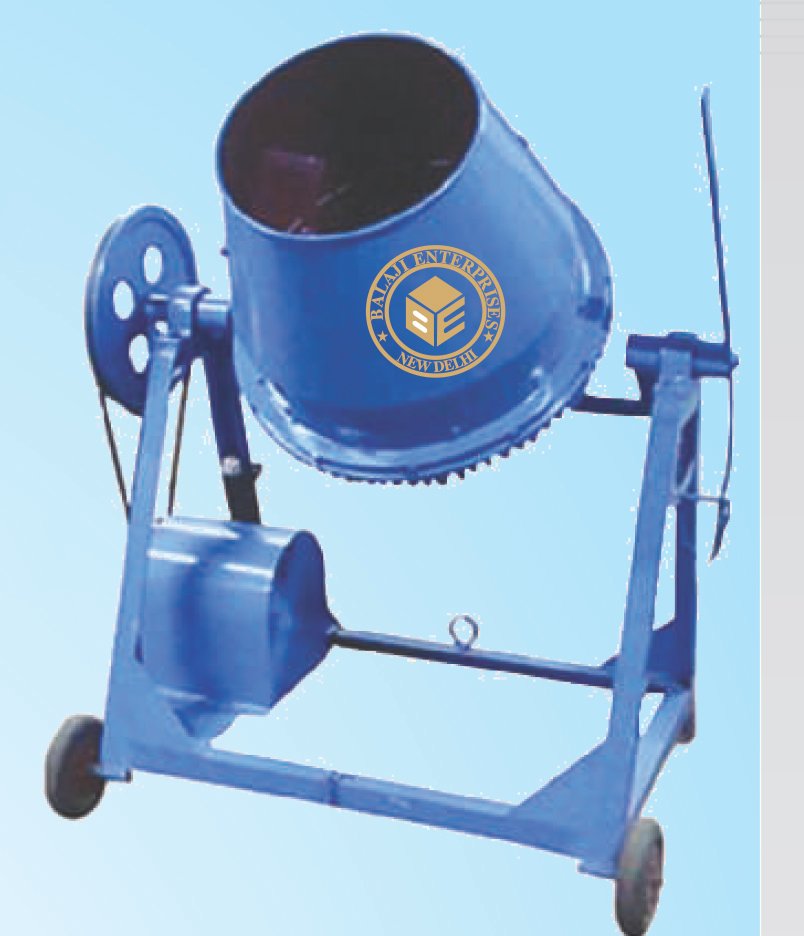
Cement Mortar Mixer
IS : 4031,1727
It is used for mixing cement pastes, mortars and pozzolanas.
Specification: The apparatus consists of an epicyclic type stainless
steel paddle imparting both planetary and revolving motion, by
means of gears. It has two speeds of 140 + 5 r.p.m. and 285 + 10
r.p.m. with planetary motions of approximately 62 r.p.m. + 5 r.p.m.
and 125 r.p.m.+/-10 r.p.m. respectively. The stand of the mixer has
arrangement to raise or lower the bowl. Complete with stainless
steel bowl of about six litres capacity. Suitable for operation on 230
volts, 50 cycles, single phase, A.C. supply.
Cone Penetrometer for Mortar
IS 2250-1965
For determining the consistency of masonry mortar Consists of a
movable bearing rod to which a cone 145mm. Long and 75mm dia
at a base is fixed. The bearing rod passes freely through a bracket
which is provided with release mechanism. A dial graduated in mm
with rack and pinion is provided for measuring the penetration.
Complete with a conical container 150mm id x 180mm deep and a
platform.
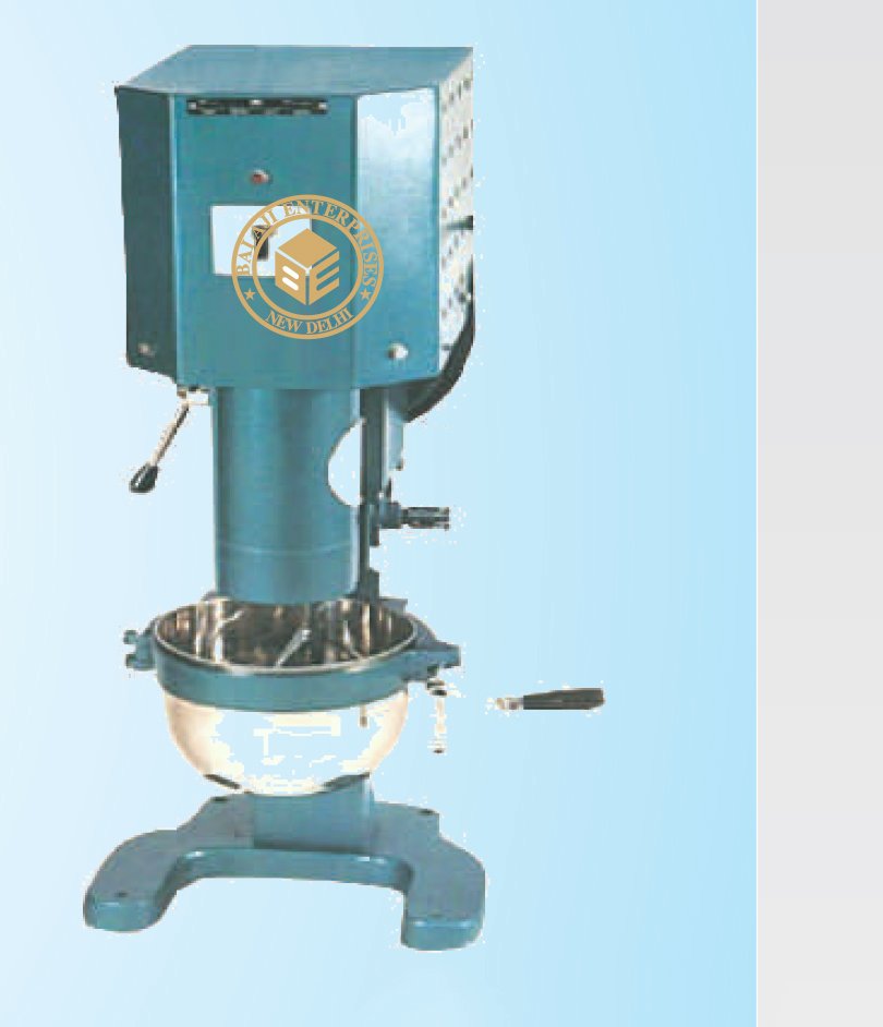
Gang Mould (Three Gang)
BS 1881-108
Moulding of 40mm, 50mm, 100mm specimens. Manufactured
from Mild Steel / Cast Iron / Bronze and supplied complete with
base plate.
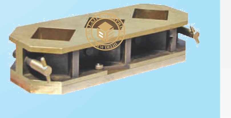
LE Chatelier Mould
IS 269, 712, 5514, 1727, 2645, 6932 (PART IX) BS 6463
It is used for the determination of soundness by expansion method
of ordinary and rapid hardening Portland cement, low heat Portland
cement and class ‘A’ Limes.
Specification : It consists of a small split cylinder forming a mould.
On either side of the split cylinder. Two parallel indicating arms with
pointed ends are attached. Supplied complete with two glass plates
and a lead weight.
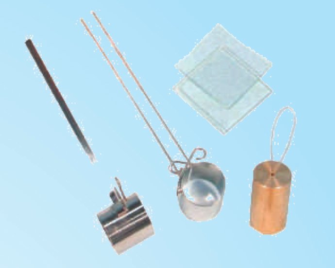
LE Chatelier Flask
IS 4031 1968, ASTM C 188
Used for finding specific gravity of hydraulic cement. Made from
Borosilicate glass. The flask is 243mm in total height, having a bulb
of 90mm dia of 250ml approximate capacity. The long neck of the
flask has at top a funnel of 50mm dia in that fits a ground glass
stopper. The neck has over-all 11mm i.d. upper portion is graduated
from 18ml to 24ml with 1 ml graduation. Just at the bottom of the
neck 1 ml capacity is marked in between there is 17 ml capacity bulb.
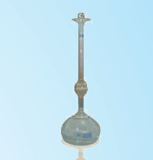
Shrinkage Bar Mould (One Gang)
IS 4031, 10086, ASTM C 227. & BS 1881.
The mould is used for casting specimens of cement & aggregate
combinations for measuring the potential expansive alkali reactivity.
Specification : The mould, which has 25 mm x 25 mm x 250 mm,
effective gauge length is made of mild steel and has accurately
machined faces. The parts of the moulds are tight fitting and firmly
held together when assembled. Supplied complete with base plate
and four stainlessteel smooth reference pins.
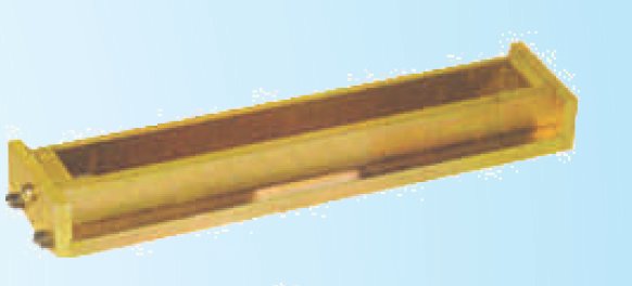
Shrinkage Bar Mould (Two Gang)
Same as above but with Two compartments assembled on angle
base plate.
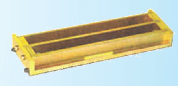
Shrinkage Bar Mould (Four Gang)
Same as above but having Four Compartments.
Note: Bar mould as above but in gun metal as well as with knurled
and threaded reference pins are also available.
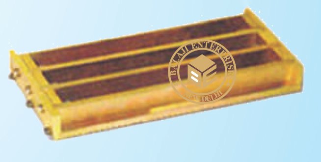
Volume Change Apparatus
ASTM C 490, IS 4031 & BS 1881
The instrument is used for determining the volume change of
cement concrete. Specification : The apparatus comprises of one
mould effective gauge length complete with base plate, four
reference pins, one length comparator frame, one stainless
reference bar with insulated grip, and one dial gauge, 0.002mm x
10mm
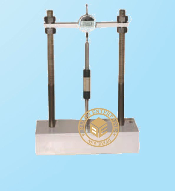
Length Comparator
IS 1199-1959, IS 4031 1968 BS 1881, ASTM C 151, C490
It is used to measure the dying shrinkage of concrete autoclave
expansion of Portland cement and potential expansive reactivity of
cement aggregate combinations in mortar bars during storage, on
self drying. Specification : The instrument consists of a channeled
base over which two vertical pillars are fixed. An adjustable cross
plate is at the top. A dial gauge, reading to .002mm x 12mm. Can be
located upon a 6.5mm. dia ball or other reference point cemented in
the specimen. On the base there is similar recessed seating in which
can be placed a second ball or reference point in the specimen.
Complete with a stainless steel standardization bar with insulated
grip and with 6.5mm dia. Balls mounted in the ends. The unit can be
supplied with an Electronic Dial Gauge at extra cost if indicated at
the time of placing the order.
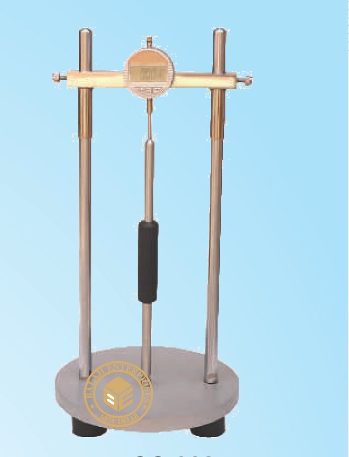
Laboratory Cement Autoclave
IS 4031-1968, IS 1624-1960 & ASTM C 151, C 141
The autoclave is suitable for conducting accelerated soundness tests
on cements or the autoclave expansion test requiring constant
steam pressure with the correspondent constant pressure. It consists
of a stainless steel cylinder with a welded heat insulated metal
housing attractively finished. The attached control unit encloses a
sensitive pressure regulator and pressure gauge. Power switches and
pilot lights for controlling the electric heating units. Inside chamber
dimensions 10.5 cm diameter x 40.5cm height suitable for operation
on 230 V, 50 Hz Single Phase A. C. supply. Supplied complete with
test bar holder, special rack to hold specimens above water level in
the autoclave and in a vertical position to expose them in the same
manner. A Digital PID Controller is fitted for controlling the desired
temperature.
Note : Ordinary laboratory cement autoclave with mild steel chambers are also
available.
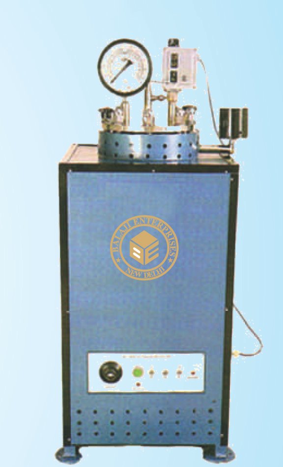
Heat of Hydration Apparatus
IS 11262-1985, ASTM C 186
This equipment is required to determine the heat of hydration of
cement as expressed in calories per gram.The equipment comprises
of the following :1) A wide mounted double walled vacuum flask
with a stop cock 38 mm & a insulating container for the flask
2) A Beckman thermometer (Range 5° C )held tightly by the cock
stopper in such a way as to avoid accidental contact with the stirrer
blade & the reading lens. To facilitate the easy removal the cock
stopper is in two halves.3) A constant speed stirrer (double bladed
propeller type)extended to within 38 mm from the bottom of the
flask.4) A funnel (Gooch type)with a stem of 6 mm inner dia & a body
approx 25 mm long and 25 mm dia is fitted to the cock stopper for
introducing the sample All the above to combine to form the
calorimeter for the determination of heat of hydration of cement.
Suitable To Operate on 230 V A.C. 50 Hz
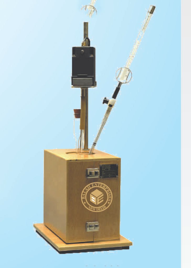
Vibrating Table
Proper compaction of cement and concrete while casting specimens
for compressive or flexural strength testing essential to achieve a
better and more consistent mixture. The cement and concrete
vibrating table top has stops along its edges to prevent moulds from
sliding off the table during operation. The maximum load capacity is
140 kg. The concrete vibrating tables are offered in 3 different table
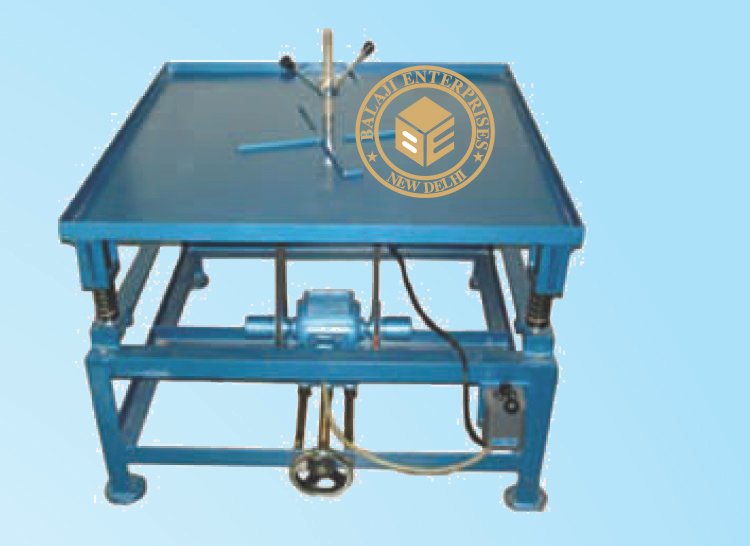
Mortar Cube Vibrating Machine
Quality Standard : As Per IS 4031, IS 10080
Vibrating Machine is used for vibrating the mix in moulds at a
frequency of 12,000 ± 400 cycles per minute. The vibrator is
mounted over 4 coiled springs and the vibrations are developed by
means of a revolving eccentric shaft. The centre of gravity of the
vibrator, including the cube mould, is either at the centre of eccentric
shaft or within 25mm below it. The simple design of the machine
facilitates easy assembly and dismantling of the cube moulds.
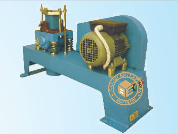
Jolting Apparatus
IS 1727 1967, IS 4031 1968, ASTM C 394, C 64
For making standard rectangular specimens of 40 x 40 x 160mm. of
Portland and pozzolana cement mortar for determining the
transverse strength. Specification : The jolting apparatus consists of
a rectangular table rigidly connected by two support arms to a
spindle at a horizontal distance of 800 mm from the centre of the
table. There is a projecting lug with a plane face on the upper face of
the table beneath which is a stop with a rounded upper surface. The
table can be raised and allowed to fall freely on the stop by a cam
which is connected to a motor and gearbox through a V-belt an
pulleys. The cam rotates at a rate of 60 Rev/Min. A stroke counter
fitted with micro-switch is provided which stops the machine after
60 Jolts. Locating pins are provided for mounting the mould
compartments on the table. The mould surmounted by the hopper
can be clamped rigidly to the table. Supplied complete with mould
and hopper. Suitable for operation on 230 Volts, Single Phase, A.C.
Supply. A Digital Preset Counter can be supplied at an extra cost.
Accessories: Steel mould with base plate having three
compartments each having 40mm x 40mm x 160mm.
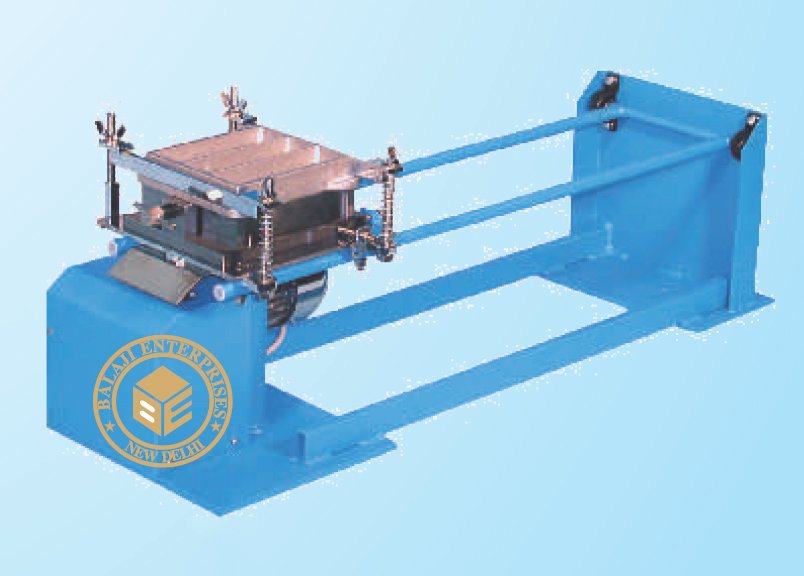
Tensile Strength Tester (Manually)
IS: 269 1950, BS 12
Using for making tensile strength test on cement briquettes.
Specification : A loading Machine, double lever type, with steel scale
marked from 0-500 Newtons in 10 Newton division. Maximum
loading capacity 5 kN. Automatic Loading system using Lead Shot.
Lead shot 15 kg supplied with the machine. Set of weights for
weighing lead shot comprising one each for weighing upto 0.5 kN, 1
kN, 1.5 kN & 2.0 kN. One standard Briquette Mould with Base Plate
also Supplied.
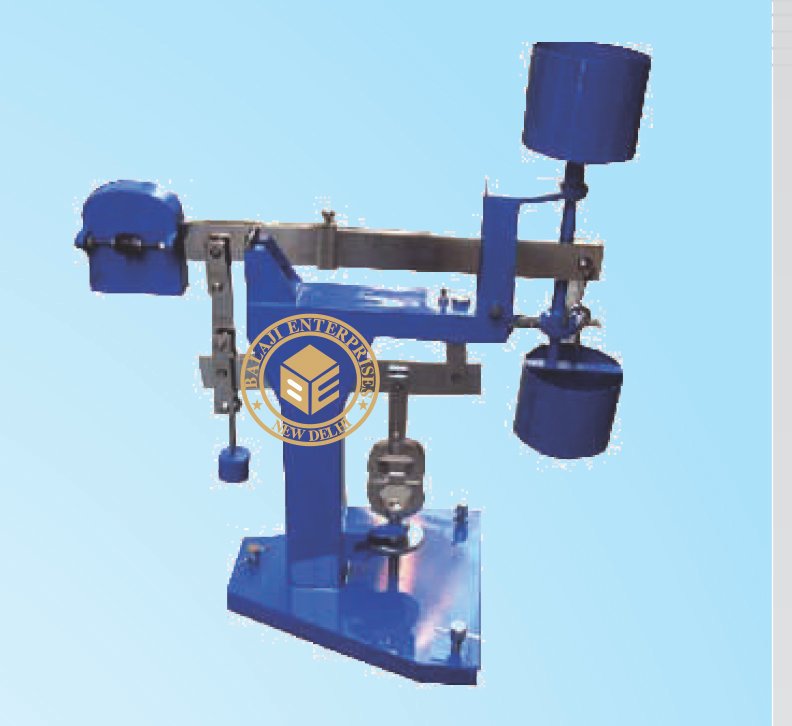
Briquette Mould (Single/Three)
IS 269 1958, Bs12.,
For casting of cement briquettes for tensile strength tests. It is a two
part split mould made of gun metal. Two thumb screws facilitate
easy and quick assembling and dismantling of the mould. The
minimum cross section of the briquettes cast is 25.4 mm x 25.4 mm.
Supplied complete with a steel base plate.
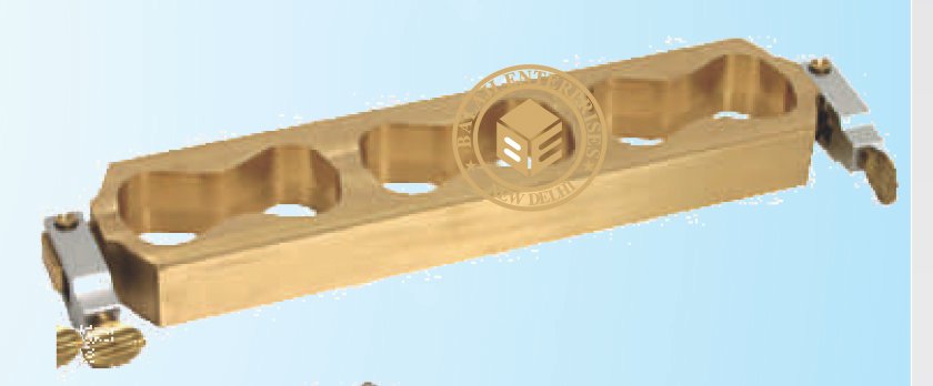
Prism Mould Three gang
IS 1727 1967, IS 4031 1968, ASTM C 394, C 64
(40.1x40x160mm) It is supplied complete with base. All parts are
marked with their dentification number for correct assembly. Each
mould is individually verified in the dimensional tolerances,
hardness, squareness, flatness & roughness.
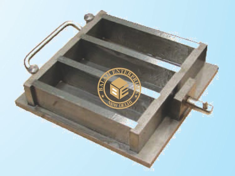
Mortar Needle Penetrometer
ASTM: C 403
It is used for finding out the rate of hardening of mortar sieved from
concrete spring and a stem graduated from 0-70 kg x 1 kg. Six
interchangeable penetration needles of areas 645, 323, 65 32 and
16mm sq. Is provided . The penetration resistance is measured by the
force exerted to penetrate the mortar by 25mm and is indicated by a
sliding ring on the stem, which is graduated. Needle shanks are
marked at every 12.5mm. Complete in a wooden carrying case.
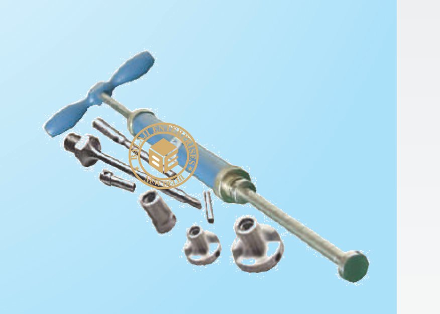
Pocket Concrete Penetrometer
ASTM C-403
For fast evaluation of the initial setting of concrete. It can be used on
light weight concrete, special roof deck mixes and concrete
additives.
Specification : Consists of a needle having face area 3/10 sq. cm.
and graduated at a distance of 25cm. The needles point is an integral
part of barrel which houses a calibrated spring. The spring is
confined in a sleeve. The resistance offered by the concrete mortar is
shown on the direct reading scale with a marker ring which holds its
2
position when released. 2 Scale range is 0-50kg/cm when the
2
penetration resistance reaches a 2 value of 35kg/cm the concrete is
assumed initially set. Supplied complete in carrying case.
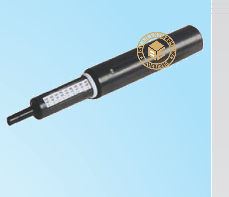
Concrete Test Hammer (Small)
The concrete test hammer is an instrument which is easy to use, for
quick and approximate measurement of the resistance to pressure of
manufactured concrete products. The principles on which it works
are based on the rebound impact of a hammer on a piston which
rests against the surface of the concrete products. The Greater the
resistance of the concrete, greater is the rebounded impact. By
reading this rebound impact on a scale and relating it to curves on
graphs supplied with the instrument, the resistance to compression
in MPa or PSI can be found, with 20% of actual.
